
Drilling apparatus and methods of using same

a technology of drilling apparatus and drilling chamber, which is applied in the direction of portable drilling machines, metal-working machine components, manufacturing tools, etc., can solve the problems of affecting production, affecting production, and affecting the quality of existing building structure components,

Inactive Publication Date: 2017-12-28
THE BOEING CO
View PDF10 Cites 11 Cited by
  • Summary
  • Abstract
  • Description
  • Claims
  • Application Information

AI Technical Summary

Benefits of technology

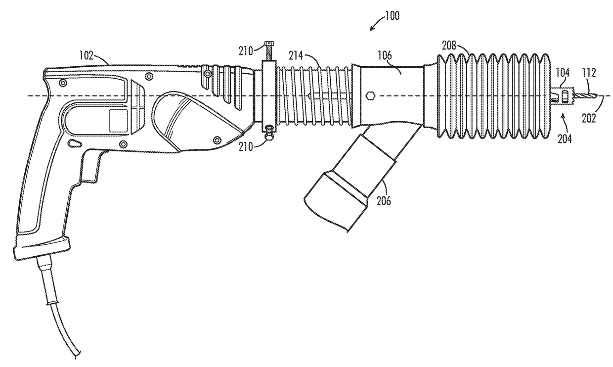
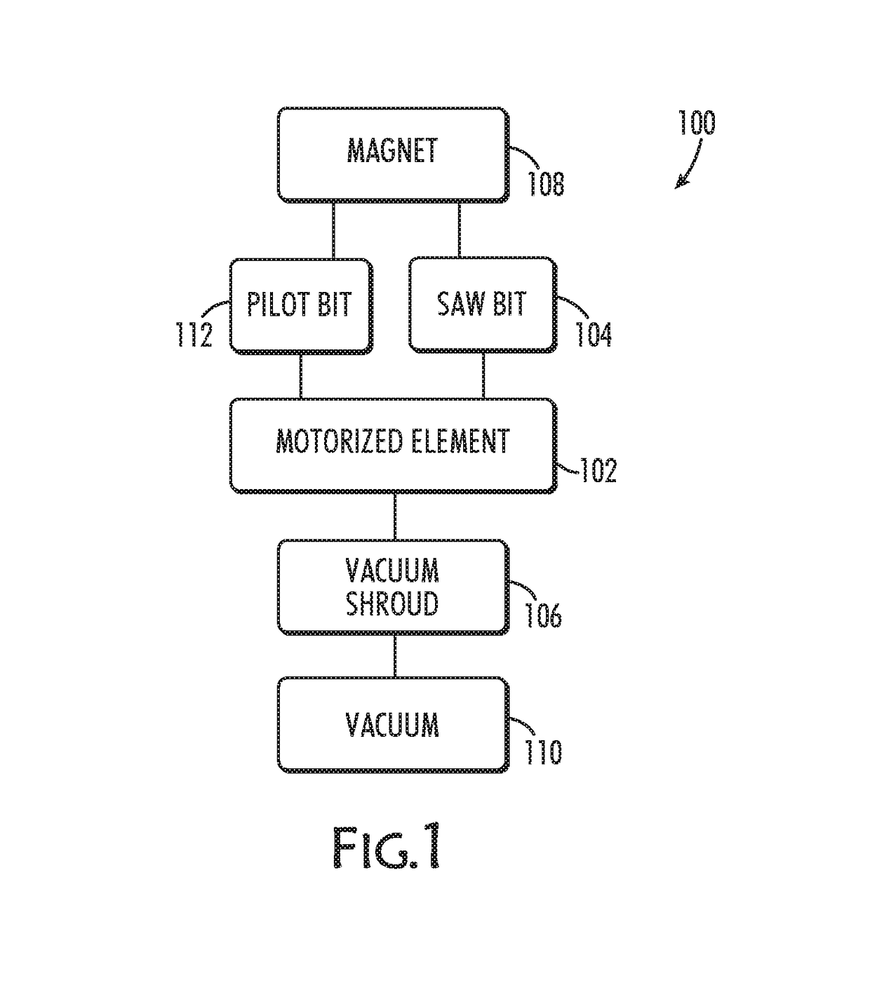
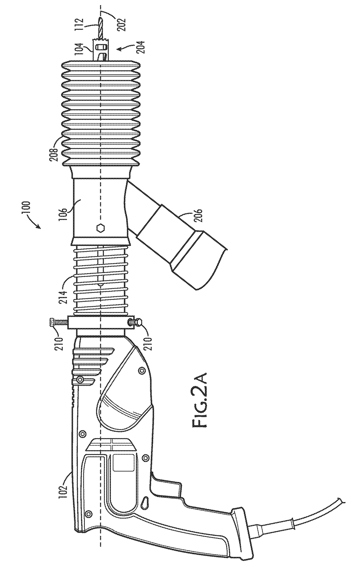
The patent describes a drilling apparatus that can remove debris from the surface being drilled. It includes a bit with a magnetic element to attract metallic debris and a vacuum shroud to remove non-metallic debris. The apparatus also has a motorized element to impart motion to the bit. A compressible boot is attached to the vacuum shroud and can be extended and contracted along the drilling apparatus's longitudinal axis. The bit has a cylindrical body with a gap and the magnetic element is placed inside the bit. The vacuum shroud is removably attached to the motorized element. The drilling apparatus kit includes a plurality of drill bits with different configurations and a vacuum shroud for each bit. The technical effect of this invention is to improve the efficiency and accuracy of drilling while minimizing debris removal.

Problems solved by technology

Working at heights and in close proximity to cranes and / or existing building structural components may pose additional issues.
Coordinating elevated work at hundreds of locations above the fabrication floor may impact production, including delays and enhanced costs.

Method used


Image

  • Drilling apparatus and methods of using same
  • Drilling apparatus and methods of using same
  • Drilling apparatus and methods of using same

Examples


Embodiment Construction

[0033]The present disclosure, in some aspects thereof, relates to power tools and, more particularly, but not exclusively, to a drilling apparatus.

[0034]Before explaining at least one aspect of the disclosure in detail, it is to be understood that the disclosure is not necessarily limited in its application to the details of construction and the arrangement of the components and / or methods set forth in the following description and / or illustrated in the drawings. The disclosure is capable of other aspects or of being practiced or carried out in various ways.

[0035]Generally, a drilling apparatus is provided which is configured, in some aspects, as a hole saw, that is, with a saw bit adapted for cutting holes into surfaces. In nominal operation of the drilling apparatus, debris is created which is removed from the cutting surface and / or prevented from falling through the hole being created by a vacuum and a magnetic element working in combination, in some aspects of the disclosure. Th...


PUM

PropertyMeasurementUnit
weightaaaaaaaaaa
compressibleaaaaaaaaaa
vacuumaaaaaaaaaa

Abstract

A drilling apparatus comprising: at least one bit; a vacuum shroud, including a compressible boot, disposed around a longitudinal axis of the apparatus and configured to be in operative communication with a vacuum attachment port; and at least one magnetic element disposed near a distal end of the apparatus and configured to attract metallic debris resulting from drilling apparatus operation.

Description

FIELD[0001]The present disclosure, in some aspects thereof, relates to power tools and, more particularly, but not exclusively, to a drilling apparatus.BACKGROUND[0002]Debris from roof assemblies may enter a fabrication facility and abatement personnel may be stationed in protective equipment on lifts under each penetration to assist with debris collection and / or removal. Working at heights and in close proximity to cranes and / or existing building structural components may pose additional issues. Coordinating elevated work at hundreds of locations above the fabrication floor may impact production, including delays and enhanced costs.BRIEF SUMMARY[0003]There is provided a drilling apparatus comprising: at least one bit; a vacuum shroud disposed around a longitudinal axis of the apparatus and configured to be in operative communication with a vacuum attachment port; and at least one magnetic element disposed near a distal end of the apparatus and configured to attract metallic debris ...

Claims


Application Information

Patent Timeline
Patent Type & Authority Applications(United States)
IPC IPC(8): B23Q11/00B23B45/00
CPCB23Q11/0071B23B45/003B23B2270/62B23Q11/0064B23B2260/10B23Q11/0046B23B2270/38B23B47/34B23B2270/30
Inventor BERGMAN, MICHAEL A.COLEMAN, JEFFREY D.
Owner THE BOEING CO
Learn More