
System and method for vehicle control using vehicular communication

a vehicle control and vehicular communication technology, applied in the direction of control devices, vehicle components, external condition input parameters, etc., can solve the problems of compromising road safety, driver is unable to see a hazard beyond a certain surrounding, and significant delays in vehicle travel

Active Publication Date: 2017-12-28
HONDA MOTOR CO LTD
View PDF11 Cites 53 Cited by
  • Summary
  • Abstract
  • Description
  • Claims
  • Application Information

AI Technical Summary

Benefits of technology

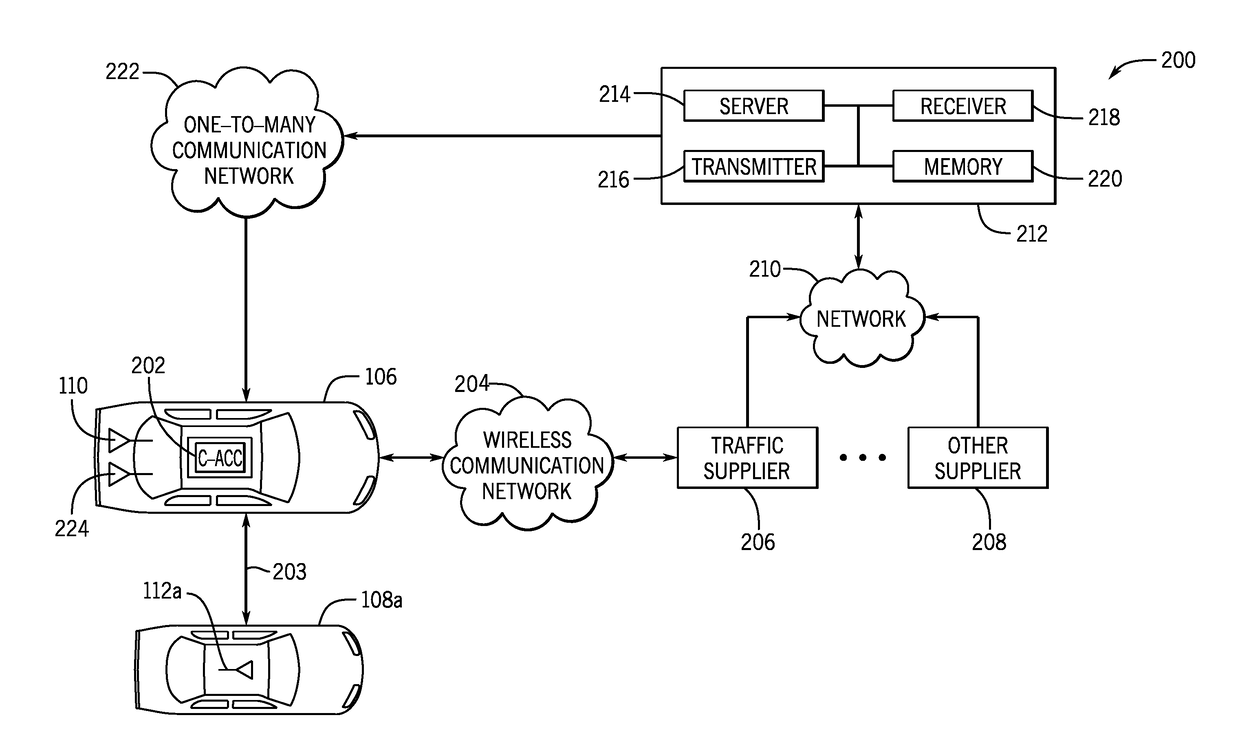
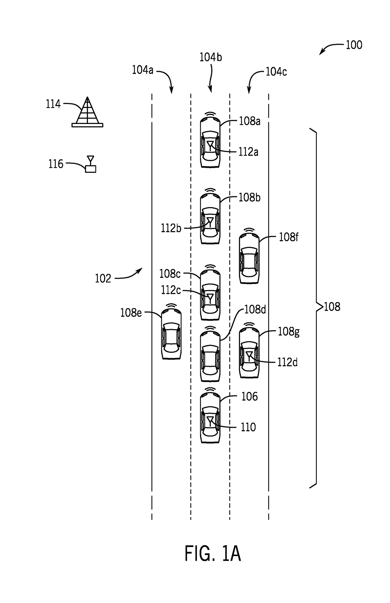
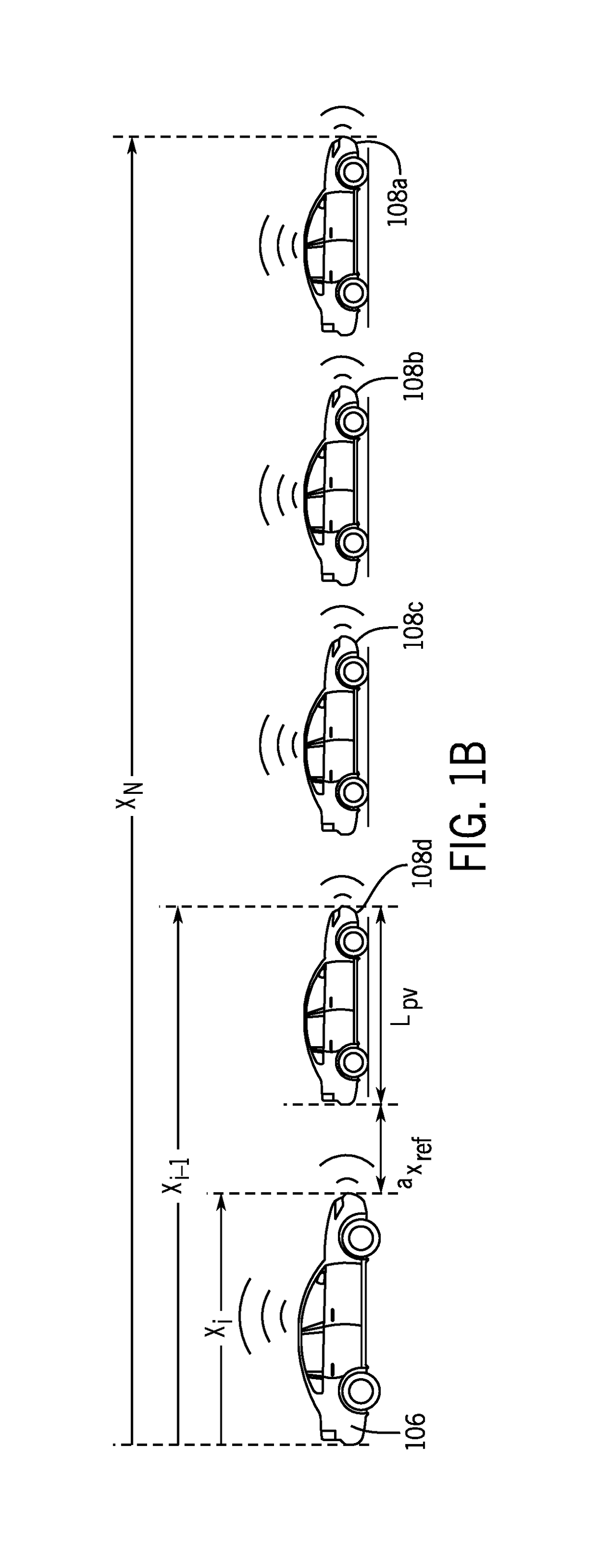
The patent describes a computer-implemented method and system for controlling a vehicle's movement relative to an preceding vehicle. The system uses sensors and wireless communication to measure the distance and velocity of the preceding vehicle. It calculates an acceleration control rate to maintain a safe distance between the host vehicle and the preceding vehicle, and sends this information to a vehicle controller to control the host vehicle's movement. The technical effect is to improve safety and efficiency during driving on the road by automatically controlling the host vehicle's motion based on the surrounding vehicle's data.

Problems solved by technology

As an illustrative example, traffic congestion, lane closures, disabled vehicles, collisions, and / or debris on a road can cause significant delays for vehicle travel and can compromise road safety.
In some circumstances, a driver is unable to see a hazard beyond a certain surrounding of the vehicle.
For example, the driver's vision may be diminished or completely obstructed by a large vehicle, traffic congestion, and / or weather conditions.
Further, the driver is generally unaware of intimate knowledge about the dynamics of other vehicles on the road and the drivers of the other vehicles.
For example, the driver may not know the speed or maneuver intentions of other vehicles on the road.
However, these sensory systems have a limited detection range within an immediate surrounding of a vehicle.

Method used


Image

  • System and method for vehicle control using vehicular communication
  • System and method for vehicle control using vehicular communication
  • System and method for vehicle control using vehicular communication

Examples


Embodiment Construction

[0038]The following includes definitions of selected terms employed herein. The definitions include various examples and / or forms of components that fall within the scope of a term and that can be used for implementation. The examples are not intended to be limiting. Further, the components discussed herein, can be combined, omitted or organized with other components or into organized into different architectures.

[0039]“Bus,” as used herein, refers to an interconnected architecture that is operably connected to other computer components inside a computer or between computers. The bus can transfer data between the computer components. The bus can be a memory bus, a memory processor, a peripheral bus, an external bus, a crossbar switch, and / or a local bus, among others. The bus can also be a vehicle bus that interconnects components inside a vehicle using protocols such as Media Oriented Systems Transport (MOST), Processor Area network (CAN), Local Interconnect network (LIN), among ot...


PUM


Abstract

A computer-implemented method for controlling a host vehicle having a vehicle control system that controls motion of the host vehicle relative to a preceding vehicle that is immediately ahead of the host vehicle. The method includes determining a relative headway distance and a relative velocity between the host vehicle and the preceding vehicle, and an acceleration rate of the preceding vehicle. The method includes receiving message packets transmitted from a leading vehicle and the message packets contain parameters of the leading vehicle including an acceleration rate of the leading vehicle. Further, the method includes calculating an acceleration control rate for the host vehicle to maintain the headway reference distance between the host vehicle and the preceding vehicle, based on the relative headway distance, the relative velocity, the acceleration rate of the preceding vehicle, and the acceleration rate of the leading vehicle. The acceleration rate is output to a vehicle controller to control motion of the host vehicle.

Description

RELATED APPLICATIONS[0001]This application claims priority to U.S. Provisional Application Ser. No. 62 / 442,333 filed on Jan. 4, 2017, which is expressly incorporated herein by reference. This application also claims priority to U.S. Provisional Application Ser. No. 62 / 442,190 filed on Jan. 4, 2017, which is also expressly incorporated herein by reference. Further, this application is a continuation-in-part of U.S. application Ser. No. 15 / 191,358 filed on Jun. 23, 2016, which is also expressly incorporated herein by reference.BACKGROUND[0002]Vehicle travel can be affected by many different variables such as, other vehicles, objects, obstructions, hazards, and environmental conditions (herein referred to as hazards). As an illustrative example, traffic congestion, lane closures, disabled vehicles, collisions, and / or debris on a road can cause significant delays for vehicle travel and can compromise road safety. A driver of a vehicle may be unaware of these different variables that aff...

Claims


Application Information

Patent Timeline
IPC IPC(8): B60W30/16B60W50/04
CPCB60W30/16B60W50/04B60W2050/046B60W2720/106B60W2550/302B60W2550/408B60W2550/308B60W2050/0024B60W2556/55B60W2554/804B60W2554/80B60W2554/801B60W2556/65B60W2554/805B60W2554/802
Inventor SAIGUSA, SHIGENOBUD'SA, JOVINSUGIMOTO, YOICHIABUGHAIDA, AMER
Owner HONDA MOTOR CO LTD
Learn More