Valve having a metal-bellows/piston unit

a technology of metal belts and valves, which is applied in the direction of valve operating means/releasing devices, indirect heat exchangers, lighting and heating apparatus, etc., can solve the problems of inability to activate in a rapid and robust manner the intermediate position, for example, the throttle position,

Inactive Publication Date: 2017-12-28
ROBERT BOSCH GMBH
View PDF7 Cites 12 Cited by
  • Summary
  • Abstract
  • Description
  • Claims
  • Application Information

AI Technical Summary

Benefits of technology

[0024]In another advantageous embodiment, the valve according to the invention is arranged in a further waste heat recovery system of an internal combustion engine. The further waste heat recovery system has a circuit conducting a working medium, wherein the circuit comprises a collecting container, a pump, a distributor valve, two evaporators in a parallel connection, an expansion machine and a condenser in the direction of flow of the working medium. The distribut

Problems solved by technology

Owing to the modes of action of the known valves, on and off positions can be activated rapidly and robustly, but

Method used


Image

  • Valve having a metal-bellows/piston unit
  • Valve having a metal-bellows/piston unit
  • Valve having a metal-bellows/piston unit

Examples


embodiment

of FIG. 1

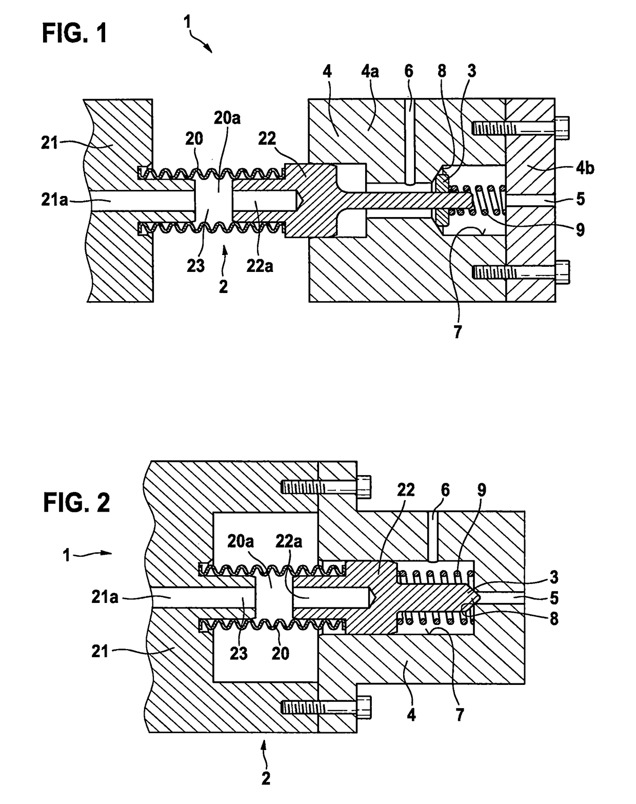
[0056]First valve position: the closing body 3 is pressed against the valve seat 8 by the valve spring 9 and thereby closes the hydraulic connection of the inlet channel 5 to the outlet channel 6.[0057]Second valve position: the closing body 3 is pressed away from the valve seat 8 by the metal-bellows / cylinder unit 2 and thereby opens the hydraulic connection from the inlet channel 5 to the outlet channel 6.

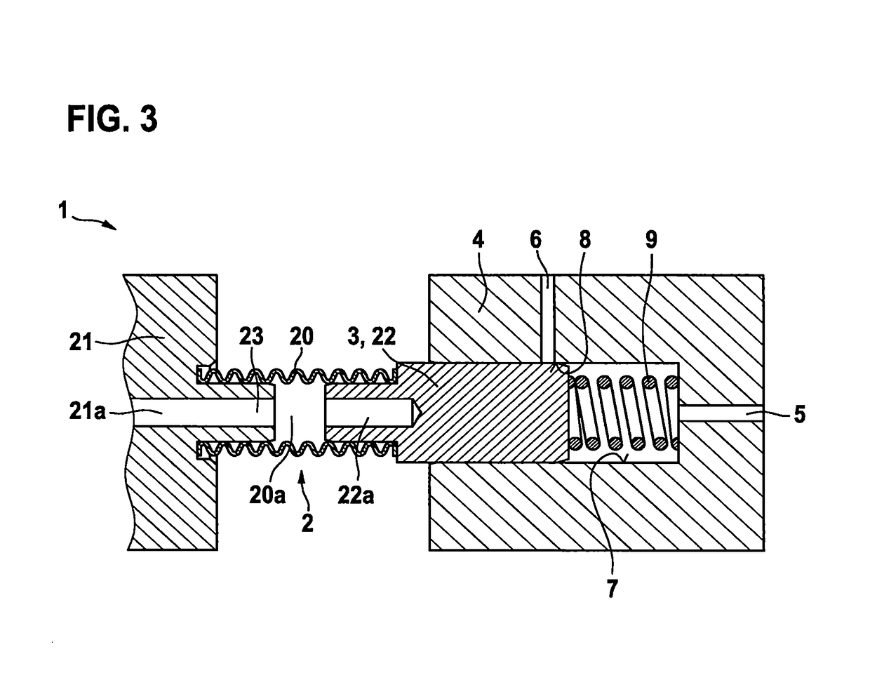
Embodiments of FIG. 2 and FIG. 3

[0058]First valve position: the closing body 3 is pressed or pushed away from the valve seat 8 by the valve spring 9 and thereby opens the hydraulic connection from the inlet channel 5 to the outlet channel 6.[0059]Second valve position: the closing body 3 is pressed against the valve seat 8 or pushed over the valve seat 8 by the metal-bellows / cylinder unit 2 and thereby closes the hydraulic connection from the inlet channel 5 to the outlet channel 6.

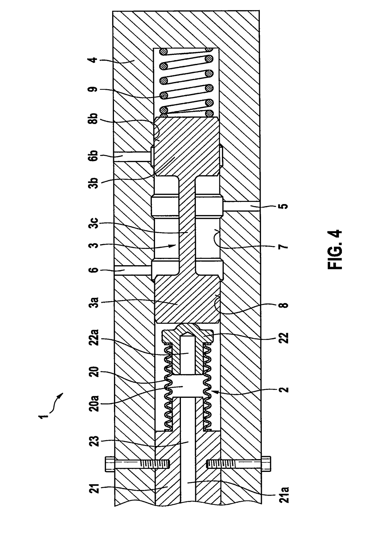
Embodiments of FIG. 4 and FIG. 5 as a 3 / 2-Way Valve

[0060]First valve position: the first c...


PUM


Abstract

The invention relates to a valve (1), comprising a valve housing (4) and a closing body (3) arranged in the valve housing (4) in such a way that the closing body can be moved longitudinally, wherein at least one inlet channel (5) and at least one outlet channel (6) are arranged in the valve housing (4). The closing body (3) interacts with a valve seat (8) formed on the valve housing (4) by means of the longitudinal motion of the closing body and thereby opens and closes at least one hydraulic connection between the at least one inlet channel (5) and the at least one outlet channel (6). The closing body (3) can be driven by means of a metal-bellows/piston unit (2), wherein the metal-bellows/piston unit (2) has a variable-length metal bellows (20) and a variable-volume working chamber (23) and wherein the metal bellows (20) bounds the working chamber (23) in a sealing manner.

Description

BACKGROUND OF THE INVENTION[0001]The invention relates to a valve having a metal-bellows / cylinder unit, wherein the metal-bellows / cylinder unit drives the valve. The valve according to the invention can be used, for example, in a waste heat recovery system of an internal combustion engine.[0002]Valves are known in many different embodiments from the prior art.[0003]A known valve comprises a valve housing and a closing body arranged in a longitudinally moveable manner in the valve housing. At least one inlet channel and at least one outlet channel are arranged in the valve housing. The closing body interacts by means of its longitudinal movement with a valve seat formed on the valve housing and thereby opens and closes at least one hydraulic connection between the at least one inlet channel and the at least one outlet channel. A valve of this type is known, for example, as a control valve for a fuel injector from laid-open application DE 102011004640 A1.[0004]Furthermore, it is known...

Claims


Application Information

Patent Timeline
IPC IPC(8): F16K11/02F16K31/126F16K11/07F28D15/02F28D15/06F28D21/00
CPCF16K11/027F16K11/0716F16K31/1262F28D15/0266F28D15/06F28D21/0003F28D2015/0291F16K11/07Y02T10/12
Inventor GLAZEWSKI, TADEUSZ
Owner ROBERT BOSCH GMBH
Why Eureka
Try Eureka