Nozzle of a Device for Contact - Free Treatment of a Running Fiber Web

Active Publication Date: 2017-12-28
VALMET TECH OY
View PDF20 Cites 1 Cited by
  • Summary
  • Abstract
  • Description
  • Claims
  • Application Information

AI Technical Summary

Benefits of technology

[0012]An object of the invention is to provide a nozzle of a device for contact-free treatment of

Problems solved by technology

Disadvantages of the prior art known arrangements are in some cases occurring mechanical uncertainties due to possibly used complicated structures and possible limitations in

Method used


Image

  • Nozzle of a Device for Contact - Free Treatment of a Running Fiber Web
  • Nozzle of a Device for Contact - Free Treatment of a Running Fiber Web
  • Nozzle of a Device for Contact - Free Treatment of a Running Fiber Web

Examples


Example

[0035]During the course of this description like numbers and signs will be used to identify like elements according to the different views which illustrate the invention. Repetition of some reference signs have been omitted in the figures for clarity reasons.

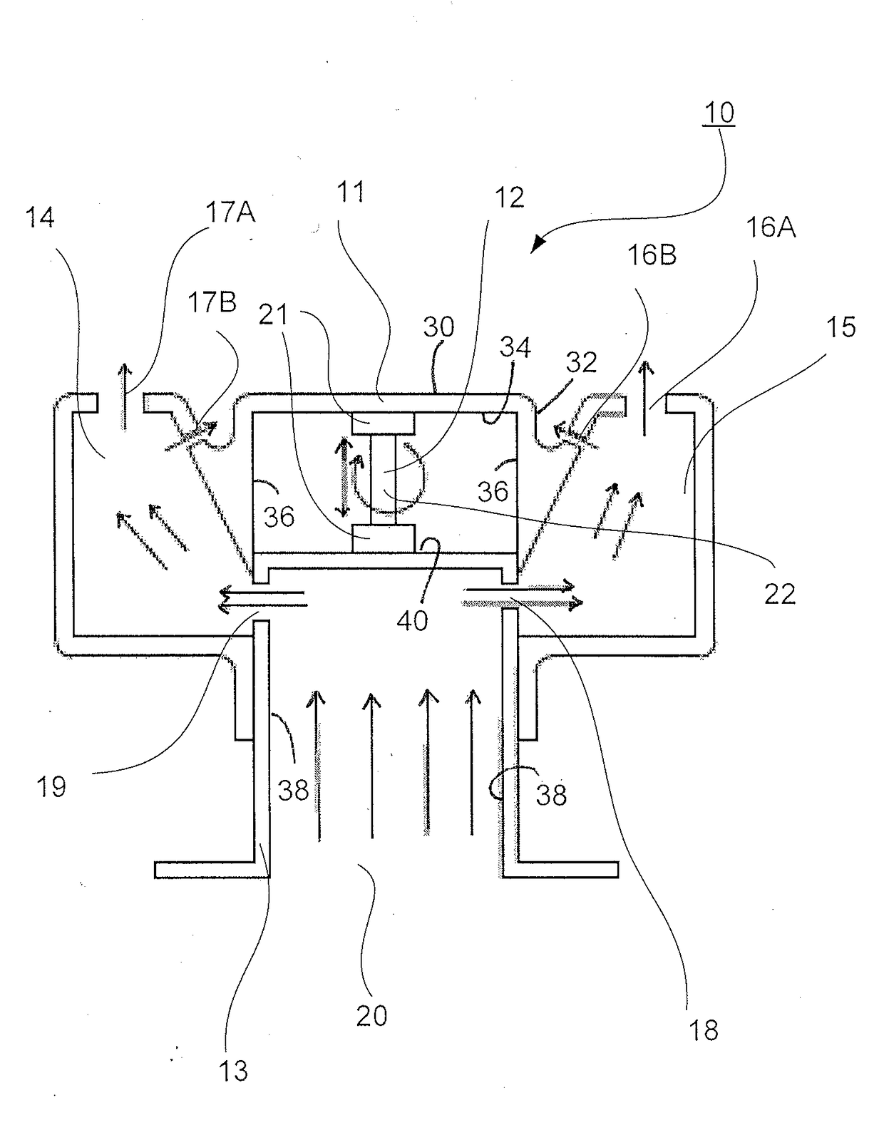
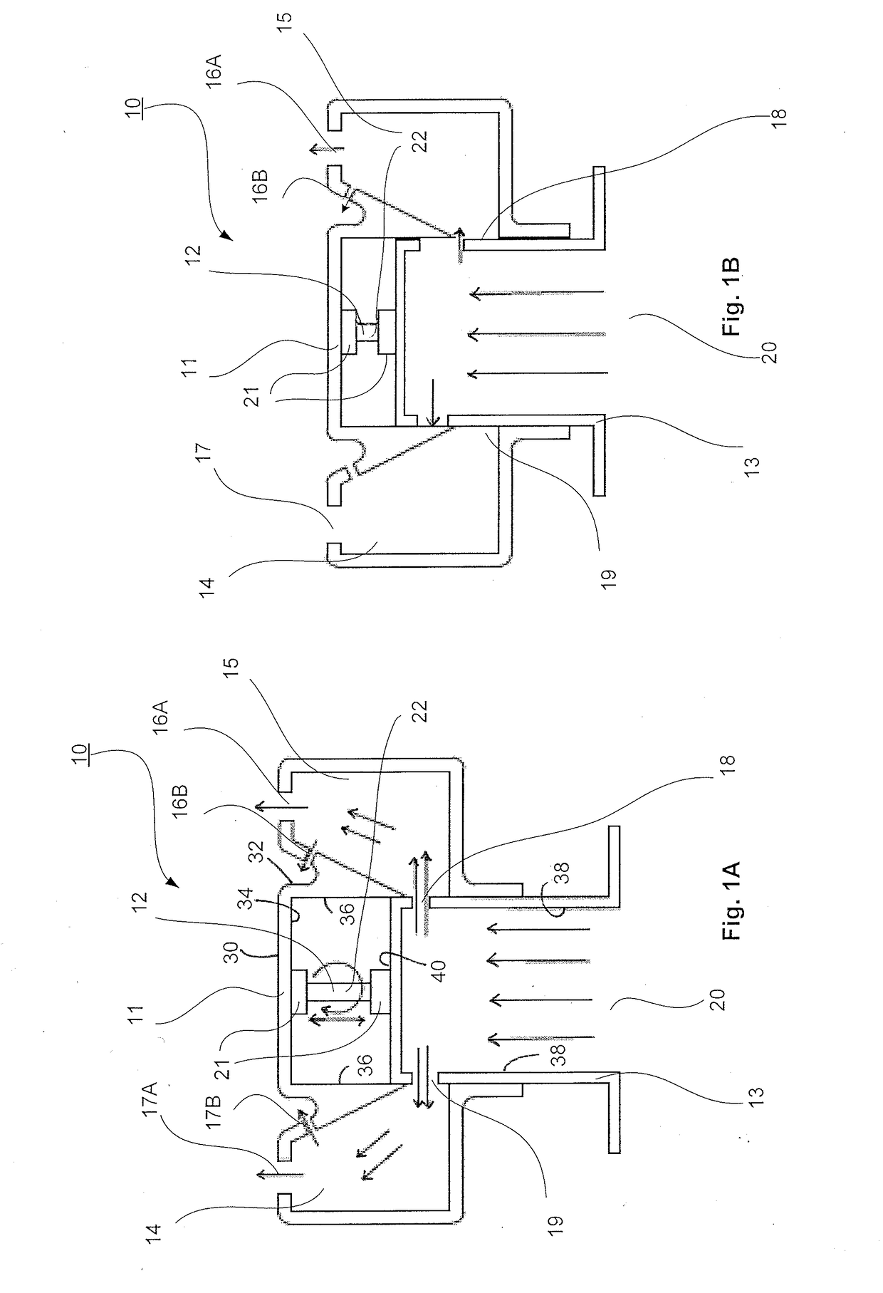
[0036]As shown in FIGS. 1A-1B the nozzle 10 comprises a main frame part 11 that forms the outer part of the nozzle 10. The main frame part 11 comprises two side chambers 14, 15 on each longitudinal side of the nozzle 10. Each side chamber 14, 15 comprises nozzle openings 16A, 16B, 17A, 17B for the air blow towards the fiber web (not shown) perpendicularly 16A, 17A and by inclined blows 16B, 17B. The main frame part 11 comprises between the side chamber 14, 15 an air channel 20 through which the air is lead to the side chambers 14, 15. The air channel 20 is formed U-shaped and its side walls have openings 18, 19 for leading the air into the side chambers 14, 15. Inside the main frame part 11 a U-shaped inner part 13 is located. B...


PUM

PropertyMeasurementUnit
Timeaaaaaaaaaa
Sizeaaaaaaaaaa
Distanceaaaaaaaaaa

Abstract

A nozzle (10) for contact-free treatment of a running web, having a main frame (11) forming an outer part of the nozzle, and two side chambers (14, 15) on each of the longitudinal sides of the nozzle (10). The side chambers having openings (17A, 17B, 16A, 16B) for the air to blow toward a fiber web. A U-shaped air channel (20), through which the air is lead to the side chambers (14, 15), located between the side chambers (14, 15), having at least one opening (19, 18) on each side wall for leading the air into the side chambers (14, 15). A U-shaped inner part (13) which is movable by a mechanism (12) comprising a screw (21) and bushings (22) to at least partially open and close the opening (18, 19).

Description

CROSS REFERENCES TO RELATED APPLICATIONS[0001]This application claims priority on EP 16175902 filed on Jun. 23, 2016 which is incorporated herein by reference.STATEMENT AS TO RIGHTS TO INVENTIONS MADE UNDER FEDERALLY SPONSORED RESEARCH AND DEVELOPMENT[0002]Not applicable.BACKGROUND OF THE INVENTION[0003]The invention relates to fiber web technology. More especially the invention relates to a nozzle of a device for contact-free support of fiber web.[0004]As known from the prior art fiber web making processes typically comprise an assembly formed by a number of apparatuses arranged consecutively in the process line. A typical production and treatment line comprises a head box, a wire section and a press section as well as a subsequent drying section and a reel-up. The production and treatment line can further comprise other devices and sections for finishing the fiber web, for example, a sizer, a calender, and a coating section. The production and treatment line also comprises at leas...

Claims


Application Information

Patent Timeline
IPC IPC(8): F26B13/20B65H23/24D21H25/06D21F5/18B65H51/16
CPCF26B13/104B65H23/24B65H51/16D21H25/06B65H2406/112D21F5/187B65H20/14D21F5/188B65H2406/1222B65H2801/84
Inventor SUOMINEN, MIKKO
Owner VALMET TECH OY
Why Eureka
Try Eureka