Unlock instant, AI-driven research and patent intelligence for your innovation.

Phase fraction measurement using continuously adjusted light source

a technology of phase fraction and light source, which is applied in the direction of fluid speed measurement, gas dispersion analysis, instruments, etc., can solve the problems of equipment damage, equipment damage, and the fact that a multiphase flowmeter utilizes a radioactive source, and may be prohibitively expensive for use in wells with relatively low production rates

Active Publication Date: 2017-12-28
SCHLUMBERGER TECH CORP
View PDF4 Cites 6 Cited by
  • Summary
  • Abstract
  • Description
  • Claims
  • Application Information

AI Technical Summary

Benefits of technology

The patent describes an apparatus and method for measuring properties of a multiphase fluid by using collimated light and a transparent window structure. The apparatus includes a collimated light source and a photodetector positioned to detect the emitted light as it passes through the multiphase fluid. The light source continuously adjusts its power based on the output of the photodetector to ensure that the emitted light is measured over an effective dynamic range greater than the actual dynamic range of the photodetector. The method involves emitting collimated light into the multiphase fluid, detecting the emitted light that passes through the fluid, and adjusting the power of the light source to cause measurement of the emitted light over an effective dynamic range greater than the actual dynamic range of the photodetector. The apparatus and method can be used to determine various properties of the multiphase fluid, such as its composition and flow rate.

Problems solved by technology

For example, the presence of solids, such as sand, in fluid can result in the erosion of equipment of a production system and even damage.
Due to challenging regulatory environments, however, the fact that a multiphase flowmeter utilizes a radioactive source may be undesirable.
In addition, current multiphase flowmeters may be prohibitively expensive for use in wells with relatively low rates of production.

Method used


Image

  • Phase fraction measurement using continuously adjusted light source
  • Phase fraction measurement using continuously adjusted light source
  • Phase fraction measurement using continuously adjusted light source

Examples


Embodiment Construction

[0021]It is to be understood that the present disclosure provides many different embodiments, or examples, for implementing different features of various embodiments. Specific examples of components and arrangements are described below for purposes of explanation and to simplify the present disclosure. These are, of course, merely examples and are not intended to be limiting.

[0022]When introducing elements of various embodiments, the articles “a,”“an,”“the,” and “said” are intended to mean that there are one or more of the elements. The terms “comprising,”“including,” and “having” are intended to be inclusive and mean that there may be additional elements other than the listed elements. Moreover, any use of “top,”“bottom,”“above,”“below,” other directional terms, and variations of these terms is made for convenience, but does not mandate any particular orientation of the components.

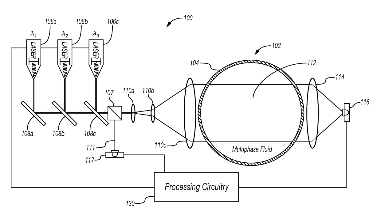
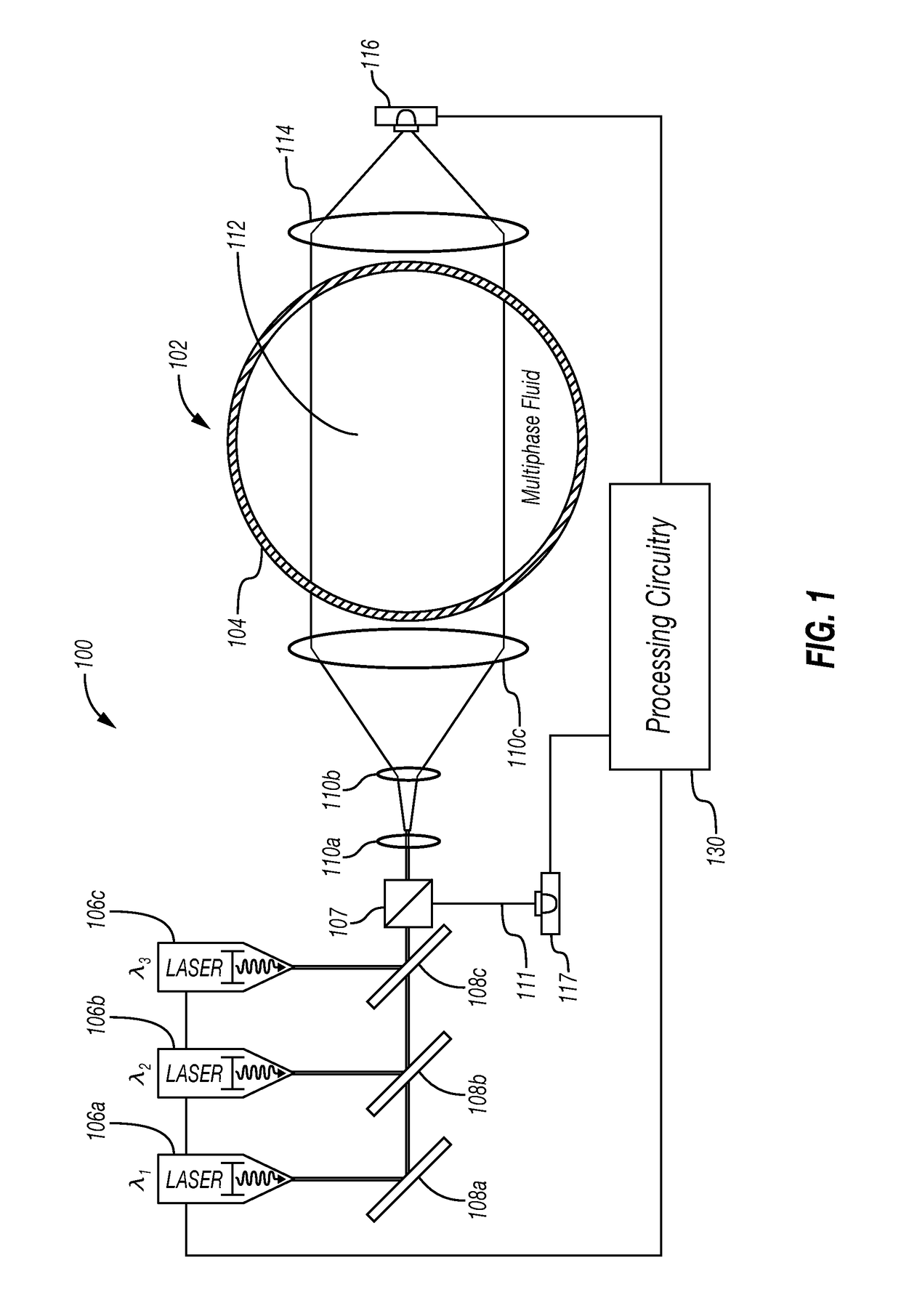
[0023]Referring initially to FIG. 1, a phase fraction determination system 100 is now described. The s...


PUM


Abstract

An apparatus includes a pipe through which a multiphase fluid flows, with a transparent window structure formed in the pipe. A collimated light source emits light through the transparent window structure into the pipe having a wavelength at which a component of a desired phase of the multiphase fluid is absorptive. A photodetector is positioned such that the emitted light passes through the multiphase fluid in the pipe to impinge upon the photodetector. The photodetector has an actual dynamic range for collimated light detection. Processing circuitry is configured to continuously adjust a power of the collimated light source dependent upon an output level of the photodetector so as to cause measurement of the emitted light over an effective dynamic range greater than the actual dynamic range, and determine a property of the multiphase fluid as a function of the power of the collimated light source.

Description

BACKGROUND[0001]This invention is related to the field of phase fraction measurement of a multiphase fluid, and, more particularly, to a multiphase flowmeter for making such phase fraction measurements.DESCRIPTION OF THE RELATED ART[0002]In hydrocarbon production, fluid produced from wells and flowing through various points of a production system is multiphasic. Thus, the fluid may have any of a gas phase, an oil phase, a water phase, and a solid phase. For a variety of reasons, it can be desirable to know the fraction of the fluid represented by each phase. For example, the presence of solids, such as sand, in fluid can result in the erosion of equipment of a production system and even damage.[0003]Multiphase flowmeters may be used to determine these phase fractions. A multiphase flowmeter may be installed in tubing and may employ a radioactive source and scintillation detector to enable measurement of the phase fractions. Such multiphase flowmeters have proven to be accurate and d...

Claims


Application Information

Patent Timeline
IPC IPC(8): G01N21/31G01N15/02G01P5/26
CPCG01N21/31G01P5/26G01N2201/12G01N2201/06113G01N2201/0633G01N15/0205G01N2015/0053G01N2015/0011G01N15/06G01N21/359G01N21/532G01N2201/0694G01N2201/1241G01N15/075
Inventor ARIFIN, ARIFINXIE, CHENG-GANG
Owner SCHLUMBERGER TECH CORP