Distribution of electric energy on a vessel

a technology for electric energy and storage vessels, applied in emergency power supply arrangements, emergency protection circuit arrangements, dc source parallel operation, etc., can solve the problems of relative large size, cost and complexity, and achieve the reduction of space and complexity, energy supply capacity, and the capacity of the plurality of backup elements.

Inactive Publication Date: 2017-12-28
SIEMENS AG
View PDF9 Cites 15 Cited by
  • Summary
  • Abstract
  • Description
  • Claims
  • Application Information

AI Technical Summary

Benefits of technology

[0011]The backup element(s) may be provided to supply essential elements, in particular essential consumers, such as thrusters, with electric energy in case of a failure in a main energy grid, which may supply electric energy to these plural consumers during normal operation. The backup elements may directly feed electric energy into the DC-circuit. Essentially, the backup elements may provide a DC power stream to the DC-circuit in case of a failure. Under normal conditions, the plural backup elements may be loaded or charged from a main grid via the DC-circuit. The plural backup elements are connected, via the plural breaker systems, to form a ring. Each one of the plural backup elements may, individually or in combination with other backup elements, be disconnected from the DC-circuit, in order to remove them from the ring. Thus, in case of a potential failure in one of the backup elements, the backup element having the failure may be disconnected from the DC-circuit, in a fast and reliable manner. This enables continued operation of the other backup elements, either to provide electric energy to consumers of the vessel, or to allow the backup elements to be charged or loaded, when the main energy grid is operating normally.
[0034]If one of the AC-bars fails, the associated backup elements may provide substitute electric energy to essential consumers. Thus, a high reliability of the energy distribution may be achieved.

Problems solved by technology

Therefore, the individual energy storage backup systems may be required to have a relatively high capacity and may therefore be relatively large in size, costly and complex.

Method used


Image

  • Distribution of electric energy on a vessel
  • Distribution of electric energy on a vessel
  • Distribution of electric energy on a vessel

Examples


Embodiment Construction

[0050]The illustration in the drawings is in schematic form. It is noted that in different figures, similar or identical elements are provided with the same reference signs or with reference signs, which are different from the corresponding reference signs only within the first digit.

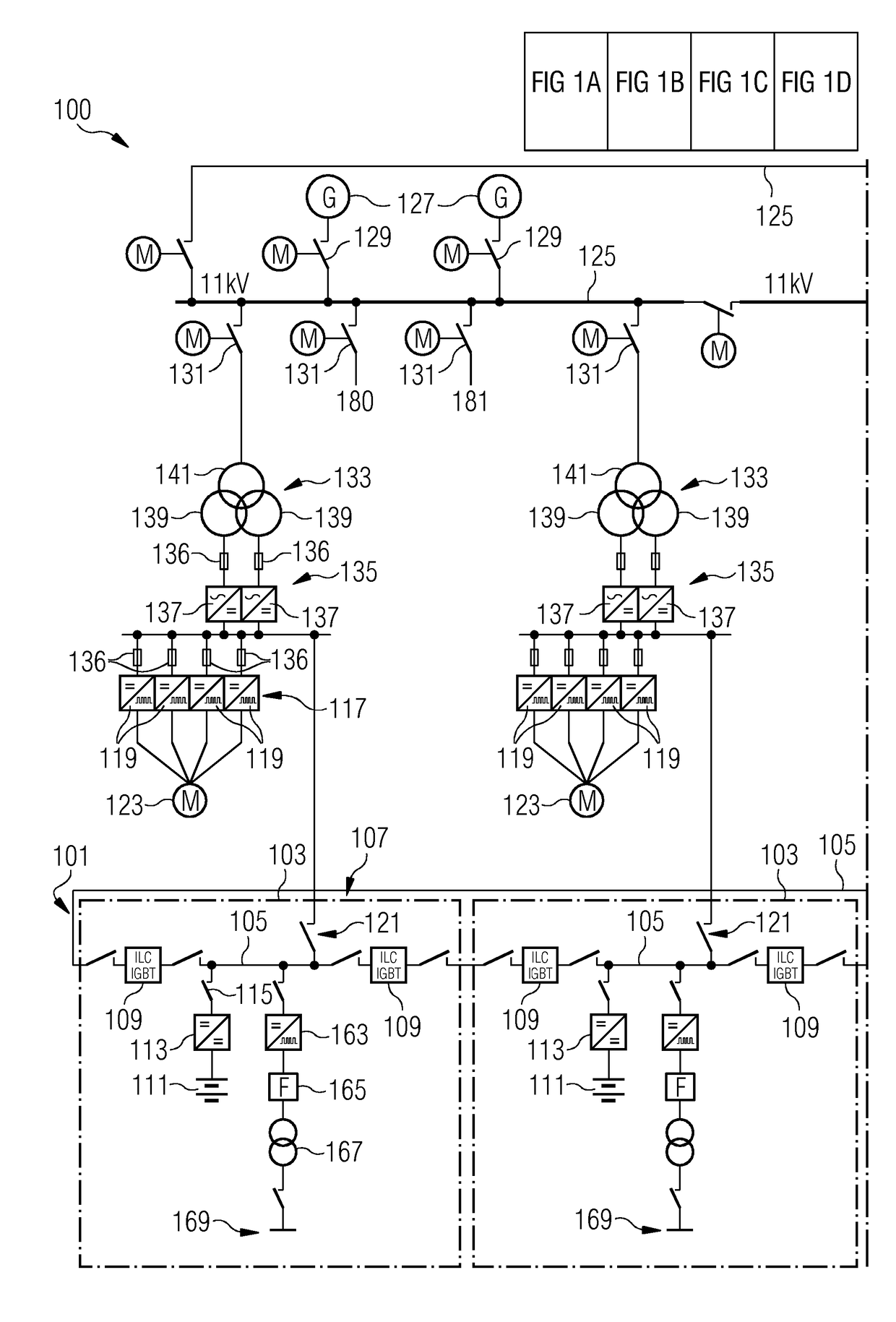
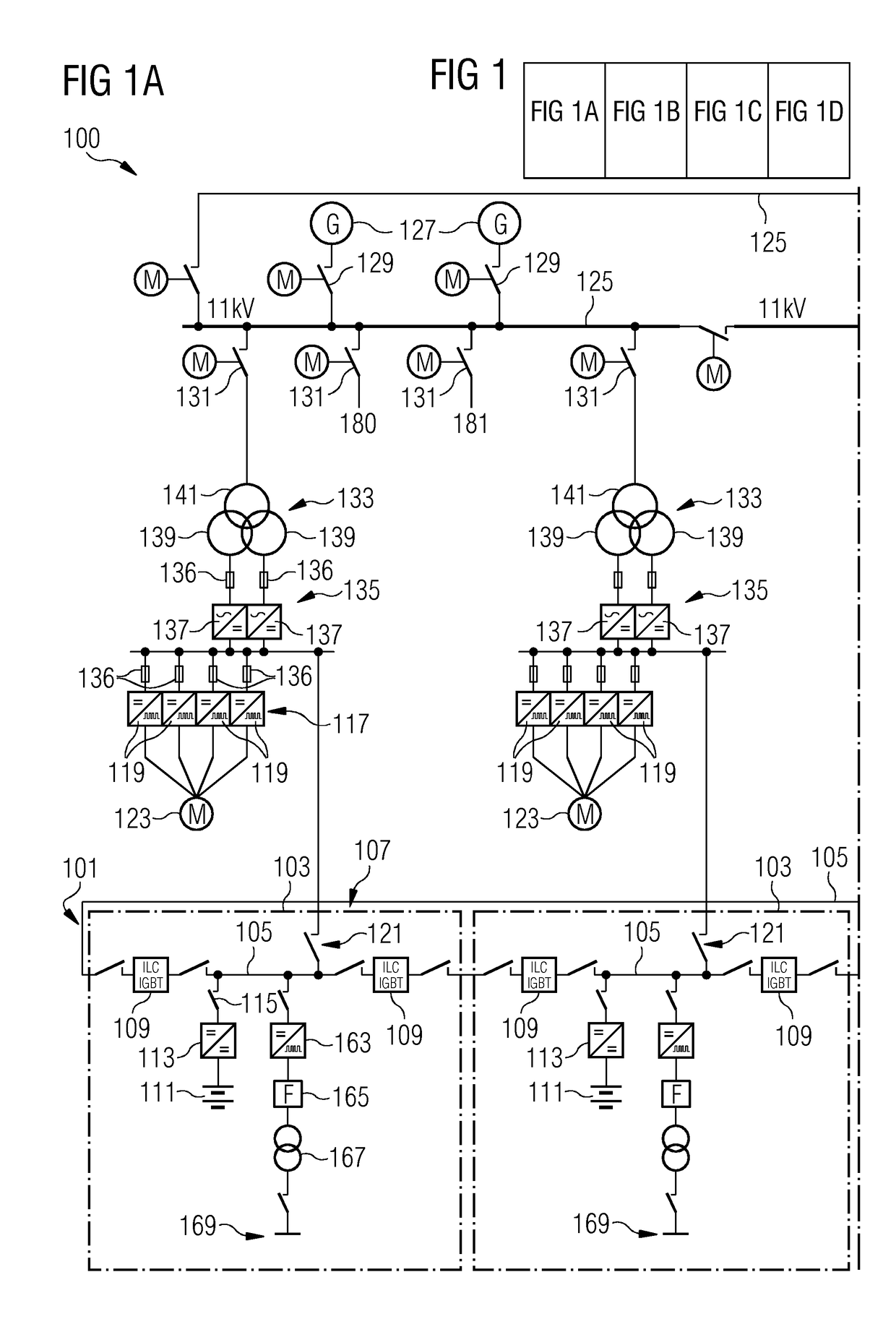
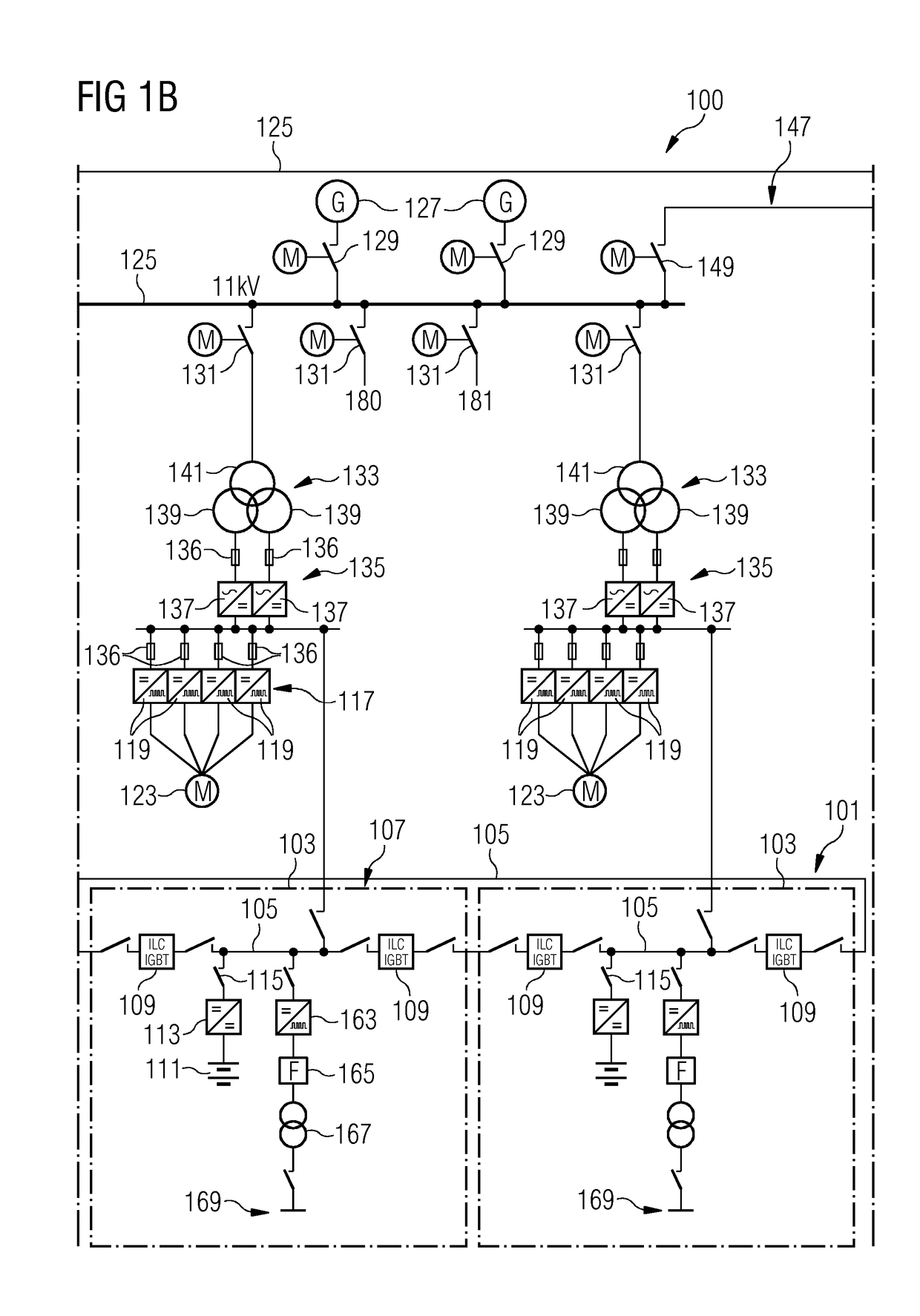
[0051]The arrangement 100 for distribution of electric energy on a vessel illustrated in FIGS. 1a to 1d comprises a DC-circuit 101 having a plurality of backup elements 103 (assembled in a similar or the same way and having similar or the same components) connected in a ring, formed by cable sections or bar sections 105. The backup elements 103 are connected in a ring during normal operation. Each backup element comprises a breaker system 107 comprising two breaker units 109 on each side of each backup element 103. Each breaker unit 109 comprises two power transistors connected in series such that each breaker system is adapted to disrupt a connection from a backup element to the DC-circuit 101 within a...


PUM


Abstract

A stored electric energy distribution arrangement for distribution of stored electric energy on a vessel having one or more AC consumers, in the event of failure of a primary electric energy supply to the AC consumers has a DC-circuit. The DC circuit has a plurality of backup electric energy storage elements connected in a ring, for supplying stored electric energy to one or more AC consumers in the event of failure of the primary electric energy supply. A plurality of breaker systems are provided in the DC circuit for disconnecting one or more backup electric energy storage elements from the DC-circuit, in the event of a fault associated with that backup element.

Description

CROSS REFERENCE TO RELATED APPLICATIONS[0001]This application is the US National Stage of International Application No. PCT / EP2016 / 051333 filed Jan. 22, 2016, and claims the benefit thereof. The International application claims the benefit of European Application No. EP15152358 filed Jan. 23, 2015. All of the applications are incorporated by reference herein in their entirety.FIELD OF INVENTION[0002]The present invention relates to an arrangement for distribution of stored electric energy on a vessel, including a ship or platform and to a method of operating an arrangement for distribution of electric energy on a vessel.BACKGROUND OF INVENTION[0003]For operating a vessel, in particular a ship or a platform, e.g. oil exploration platform, electric energy may need to be distributed to a number of consumers, such as thrusters and pumps, which may need to be operated on a vessel. The vessel or platform may comprise essential components that need to be supplied with electric energy even ...

Claims


Application Information

Patent Timeline
Patent Type & Authority Applications(United States)
IPC IPC(8): H02J3/00H02H3/087H02H3/32H02H7/26
CPCH02J3/006H02H7/268H02H3/325H02H3/087H02J9/061H02J9/062H02J9/08H02J9/068H02H3/26H02H3/32H02J1/10H02J3/0073
Inventor HAUGAN, ESPENKJESBU, HARALD
Owner SIEMENS AG
Why Eureka
Try Eureka