Implementing logical network security on a hardware switch

a hardware switch and network security technology, applied in the direction of transmission, electrical equipment, etc., can solve the problems of large amount of cache memory on the hardware, data flow cannot be easily managed, and stateful firewall mechanism cannot be efficiently employed by the hardware switch

Active Publication Date: 2018-01-04
NICIRA
View PDF2 Cites 75 Cited by
  • Summary
  • Abstract
  • Description
  • Claims
  • Application Information

AI Technical Summary

Benefits of technology

[0002]Some embodiments provide a method for applying a security policy defined for a logical network to a managed hardware forwarding element (MHFE) that integrates physical workloads (e.g., one or more physical machines connected to the MHFE) with the logical network. In some embodiments, the method applies the security policy to the MHFE by generating a set of access control list (ACL) rules based on the security policy's definition and configuring the MHFE (e.g., a top of rack switch, a physical router, etc.) to apply the ACL rules on the network traffic that is forwarded to and / or from the physical machines. The MHFE, along with a set of managed software forwarding elements (MSFEs) that executes on a set of host machines, implement a set of logical forwarding elements (LFEs) of the logical network. The set of LFEs logically connects the physical machines to a set of end machines that executes on the host machines. Each host machine executes an MSFE and may host a subset of the end machines (e.g., virtual machines, containers, etc.).

Problems solved by technology

One of the challenges in today's SDN systems is adding physical workloads (e.g., one or more physical machines) to logical networks and applying the same logical network rules and policies to the physical workloads.
Unlike software switches, a stateful firewall mechanism cannot be efficiently employed by a hardware switch.
This is because, hardware switches are stateless and as such network data flows cannot be easily managed on them (i.e., keeping the state of every data flow requires a large amount of cache memory on the hardware switch which could be costly).

Method used


Image

  • Implementing logical network security on a hardware switch
  • Implementing logical network security on a hardware switch
  • Implementing logical network security on a hardware switch

Examples


Embodiment Construction

[0030]In the following detailed description of the invention, numerous details, examples, and embodiments of the invention are set forth and described. However, it should be understood that the invention is not limited to the embodiments set forth and that the invention may be practiced without some of the specific details and examples discussed.

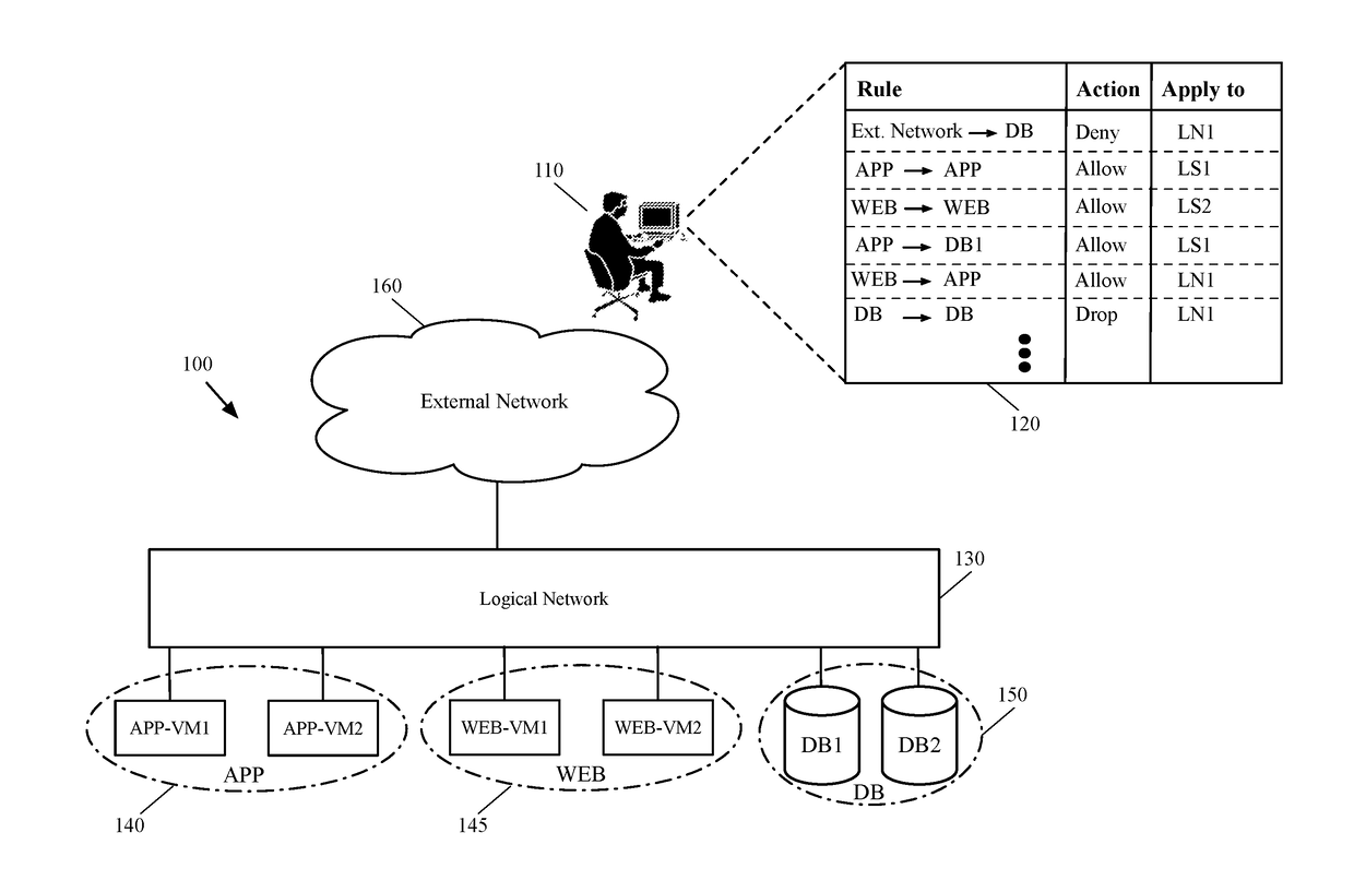
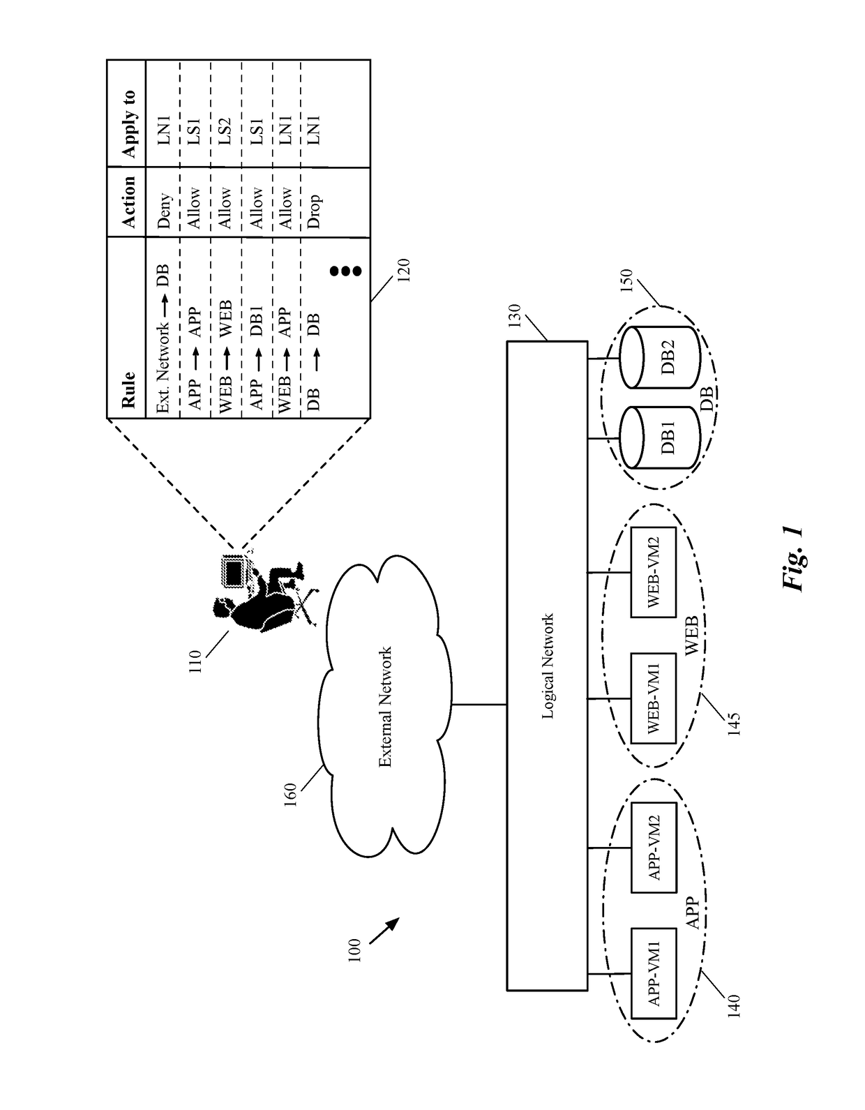
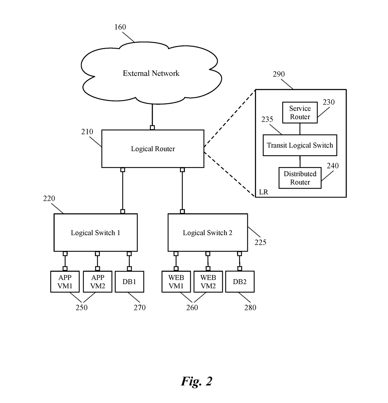
[0031]Some embodiments provide a method for applying a security policy defined for a logical network to a managed hardware forwarding element (MHFE) that integrates physical workloads (e.g., one or more physical machines connected to the MHFE) with the logical network. In some embodiments, the method applies the security policy to the MHFE by generating a set of access control list (ACL) rules based on the security policy's definition and configuring the MHFE (e.g., a top of rack switch, a physical router, etc.) to apply the ACL rules on the network traffic that is forwarded to and / or from the physical machines. The MHFE, along with a set of...


PUM


Abstract

Some embodiments provide a method for configuring a hardware switch to implement a security policy associated with a logical router of a logical network. The method receives a logical router definition. The logical router logically connects a physical machine, connected to a physical port of the hardware switch, to several VMs that execute on a set of host machines. The method defines a set of routing components for the logical router, each of which, has several interfaces. The method receives a security policy that includes a set of security rules for the physical machine and populates an ACL table with ACL rules data generated based on the received set of security rules. The method then for at least one interface of one of the routing components, generates linking data that links a set of one or more ACL rules in the ACL table to the interface of the routing component.

Description

BACKGROUND[0001]There is a growing movement, driven by both industry and academia, towards a new network control paradigm called Software-Defined Networking (SDN). A logical (virtual) network that is implemented for a tenant of a hosting system is a good example for a software-defined network. Such a logical network connects a set of tenant's virtual machines that execute on one or more host machines, to each other and to other logical and / or physical networks. One of the challenges in today's SDN systems is adding physical workloads (e.g., one or more physical machines) to logical networks and applying the same logical network rules and policies to the physical workloads. For example, firewall rules can be applied to the virtual machines of a logical network in a distributed manner (e.g., through a security agent). Unlike software switches, a stateful firewall mechanism cannot be efficiently employed by a hardware switch. This is because, hardware switches are stateless and as such...

Claims


Application Information

Patent Timeline
Patent Type & Authority Applications(United States)
IPC IPC(8): H04L29/06
CPCH04L63/0236H04L63/101H04L63/0263H04L63/20
Inventor CHANDA, ANUPAMDAVIE, BRUCE
Owner NICIRA
Why Eureka
Try Eureka