Torque position-limiting device

a technology of torque position and limiting device, which is applied in the direction of friction gearing, belt/chain/gearing, friction gearing, etc., can solve the problems of inability of mobile electronic devices to be in line with the concept of light, thin, short and small mobile electronic device characteristics, and achieve the effect of simple structure and different amount of friction for

Inactive Publication Date: 2018-01-11
HORNG CHIN HSING
View PDF2 Cites 0 Cited by
  • Summary
  • Abstract
  • Description
  • Claims
  • Application Information

AI Technical Summary

Benefits of technology

[0005]The present invention has been accomplished under the circumstances in view. It is therefore the main object of the present invention to provide a torque position-limiting device, which has a simple structure and is practical for use in a mobile electronic device having light, thin, short and small characteristics and, which comprises a pivot member and a position-limiting member pivotally coupled to the pivot member and capable of generating a friction force between the position-limiting member and the pivot member for stepless positioning when it is rotated.
[0006]It is another object of the present invention to provide a torque position-limiting device, which generates a different amount of friction force when the position-limiting member is turned about the pivot member in the reversed direction, and thus, the torque position-limiting device can match with the torque required to open or close the mobile electronic device.

Problems solved by technology

However, a latch-based or bump interference-based positioning means has the drawbacks of complicated structure and manufacturing process, operation inconvenience, making the mobile electronic device unable to be in line with the concept of light, thin, short and small mobile electronic device characteristics.

Method used


Image

  • Torque position-limiting device
  • Torque position-limiting device
  • Torque position-limiting device

Examples


first embodiment

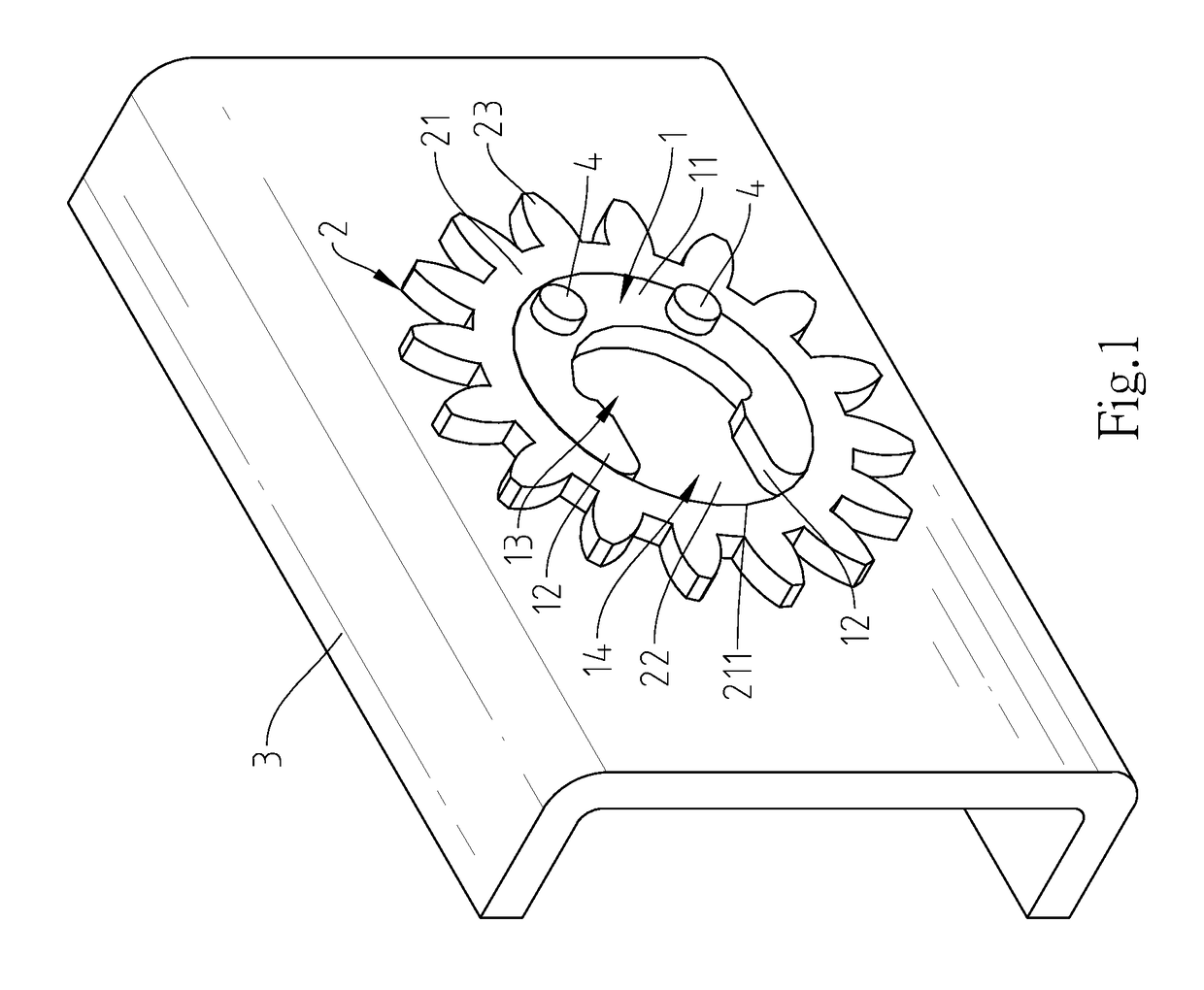
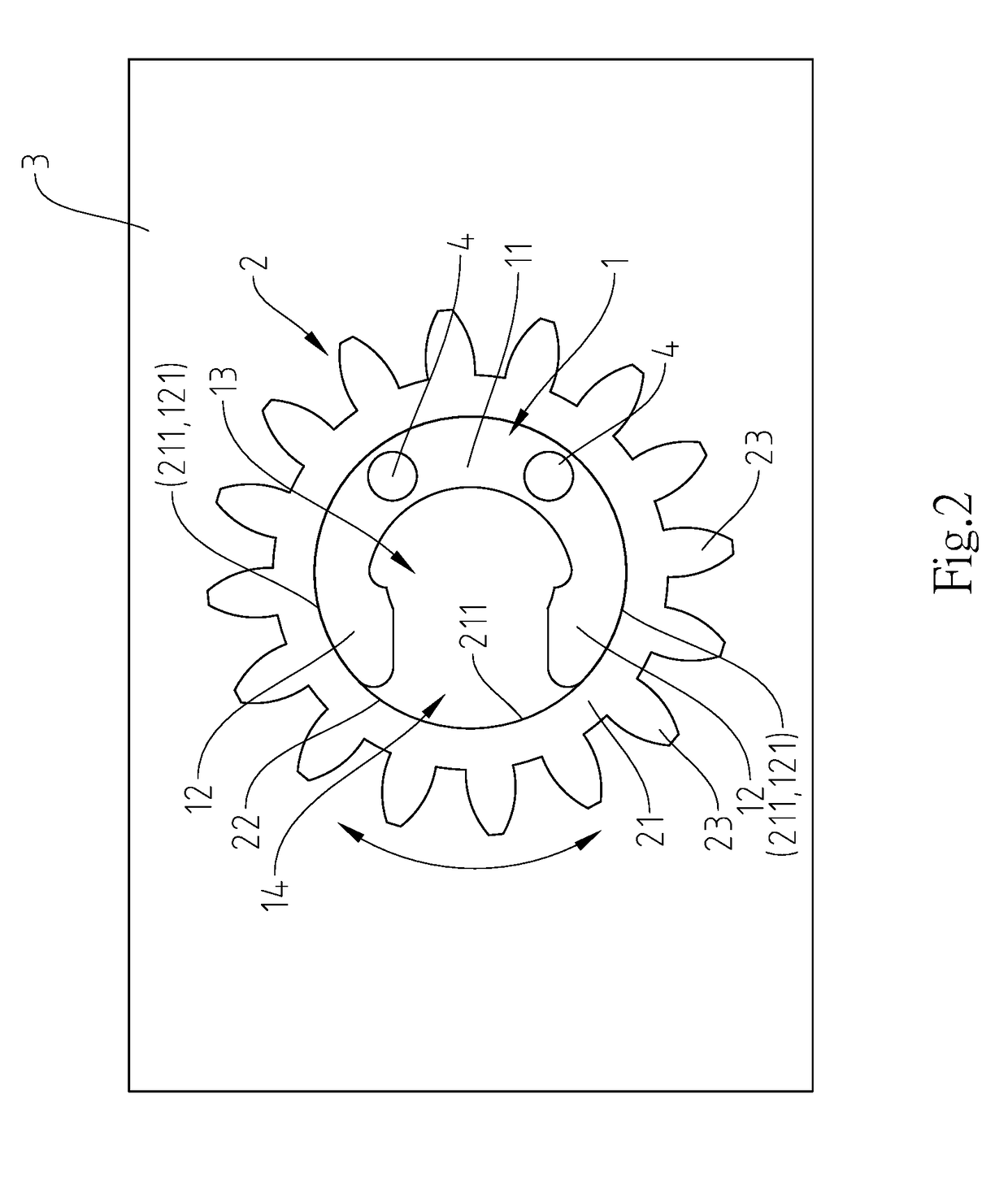
[0018]Referring to FIGS. 1-3, a torque position-limiting device in accordance with the present invention is shown. The torque position-limiting device comprises a pivot member 1 and a position-limiting member 2.

[0019]The pivot member 1 comprises a base portion 11, a plurality of mounting holes 111 cut through opposing front and back surfaces of the base portion 11, two elastically compressible arms 12 respectively extended from two distal ends of the base portion 11 to face toward each other, a flexible space 13 surrounded by the elastically compressible arms 12 and the base portion 11, a smoothly curved bearing surface 121 located on an outer side of each of the two elastically compressible arms 12 opposite to the flexible space 13, and a gap 14 defined between the two elastically compressible arms 12 in communication with the flexible space 13.

[0020]The position-limiting member 2 comprises a body portion 21, a circular pivot hole 22 defined in the body portion 21, an abutment surf...

second embodiment

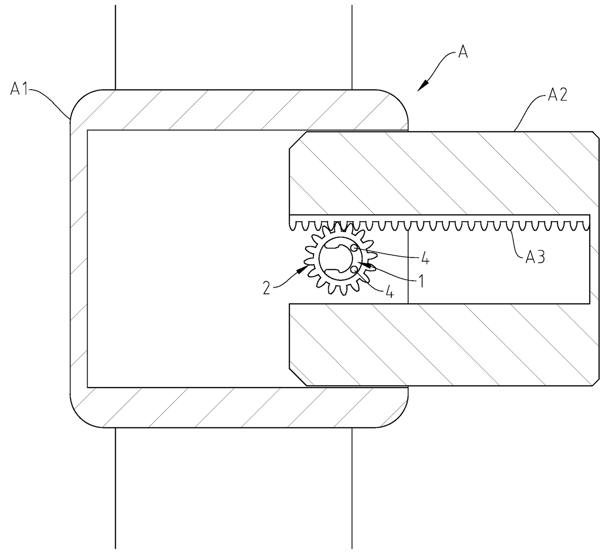
[0025]Referring to FIGS. 9 and 10 and FIG. 7 again, the torque position-limiting device in accordance with the present invention can be used in a smartwatch B. As illustrated, affix the base portion 51 of the pivot member 5 to a housing B1 of the smartwatch B with fastening members 4 to keep the outer ring gear portion 23 of the position-limiting member 2 in mesh with a tooth rack B3 at one lateral side of a screen B2 in the housing B1. When the user pulls the screen B2 out of the housing B1 or pushes the screen B2 back into the inside of the housing B1, the tooth rack B3 will be moved with the screen B2 to push the outer ring gear portion 23 of the position-limiting member 2, turning the position-limiting member 2 about the pivot member 5. When the user releases the hand from the screen B2, the screen B2 is immediately held down in position by the friction force between the first and second smoothly curved bearing surface 521;531 and the abutment surface 211. Further, it requires d...


PUM


Abstract

A torque position-limiting device includes a pivot member affixed to an external substrate, two compressible arms respectively extended from two opposite ends thereof toward each other with a gap defined therebetween and a smoothly curved bearing surface located on an outer side of each elastically compressible arm, and a position-limiting member including a circular pivot hole pivotally coupled to the pivot member, an abutment surface located on an inner perimeter thereof and abutted against each smoothly curved bearing surface of the pivot member and an outer ring gear portion located on an opposing outer perimeter thereof and drivable by an external force to turn the position-limiting member about the pivot member and to further cause generation of a friction force between each smoothly curved bearing surface of the pivot member and the abutment surface of the position-limiting member.

Description

BACKGROUND OF THE INVENTION[0001]1. Field of the Invention[0002]The present invention relates to hinge technology and more particularly, to a torque position-limiting device, which comprises a pivot member affixed to a substrate, and a position-limiting member pivotally coupled to the pivot member and rotatable by an external force to cause generation of a friction force between the position-limiting member and the pivot member for stepless positioning when the external force disappears.[0003]2. Description of the Related Art[0004]In order to make a mobile electronic device more portable for convenient use, the prior art is to house the control unit in the housing of the mobile electronic device to reduce the dimension of the mobile electronic device, or to install the screen or keyboard in a slidable manner through the transmission of a gear and rack mechanism. In this design, a latch-based or bump interference-based positioning means is needed for holding the screen or keyboard in...

Claims


Application Information

Patent Timeline
Patent Type & Authority Applications(United States)
IPC IPC(8): F16H35/00F16H19/04
CPCF16H35/00F16H2035/006F16H2019/046F16H19/04
Inventor HORNG, CHIN-HSING
Owner HORNG CHIN HSING
Why Eureka
Try Eureka