Electro-Optical Distance Meter

a distance meter and optical technology, applied in the field of optical distance meter, can solve the problems of distance measurement error and distance measurement error, and achieve the effect of improving reliability with respect to environmental changes and improving distance measurement accuracy

Active Publication Date: 2018-01-11
KK TOPCON
View PDF3 Cites 1 Cited by
  • Summary
  • Abstract
  • Description
  • Claims
  • Application Information

AI Technical Summary

Benefits of technology

[0021]According to the present invention, the electro-optical distance meter comprises a light source for emitting a distance measuring light, a distance measuring optical system for projecting the distance measuring light to an object to be measured, for receiving a distance measuring light from the object to be measured and for leading to a photodetector, an internal reference optical system for leading a part of the distance measuring light as an internal reference light to the photodetector, and an arithmetic processing unit for performing a distance measurement based on a light receiving result of the distance measuring light and a light receiving result of the internal reference light wherein the internal reference optical system comprises a condenser lens for condensing the internal reference light, a scattering plate for scatteri

Problems solved by technology

Therefore, the quality of the received light of the internal reference light differs from the light receiving quality of the distance measuring tight, as a result, it is possible to cause a distance measurement error.
Further, a support position of the photodetector in the electro

Method used


Image

  • Electro-Optical Distance Meter
  • Electro-Optical Distance Meter
  • Electro-Optical Distance Meter

Examples


first embodiment

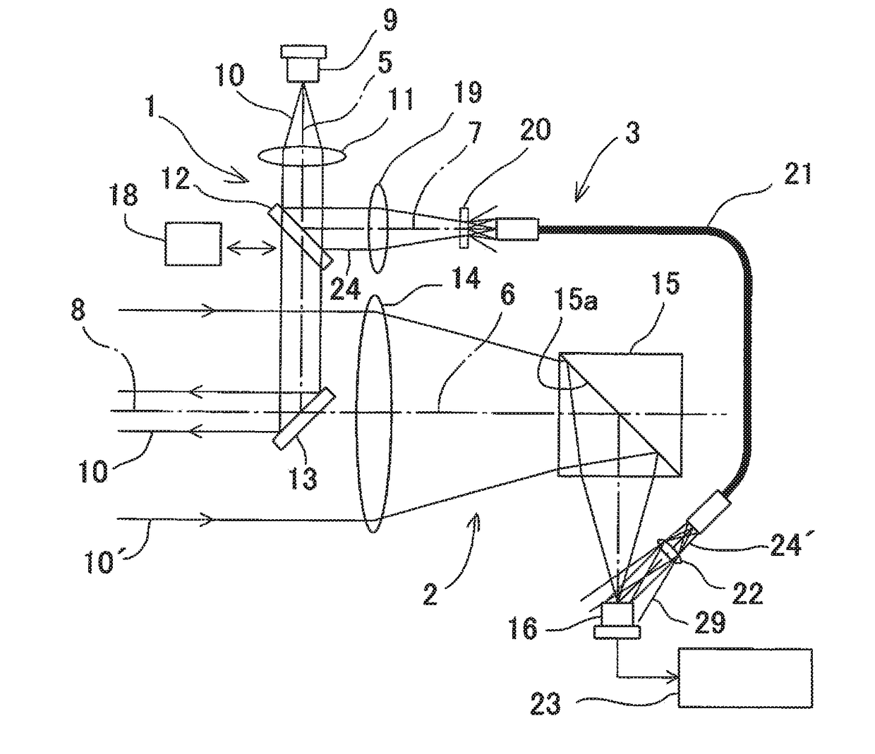
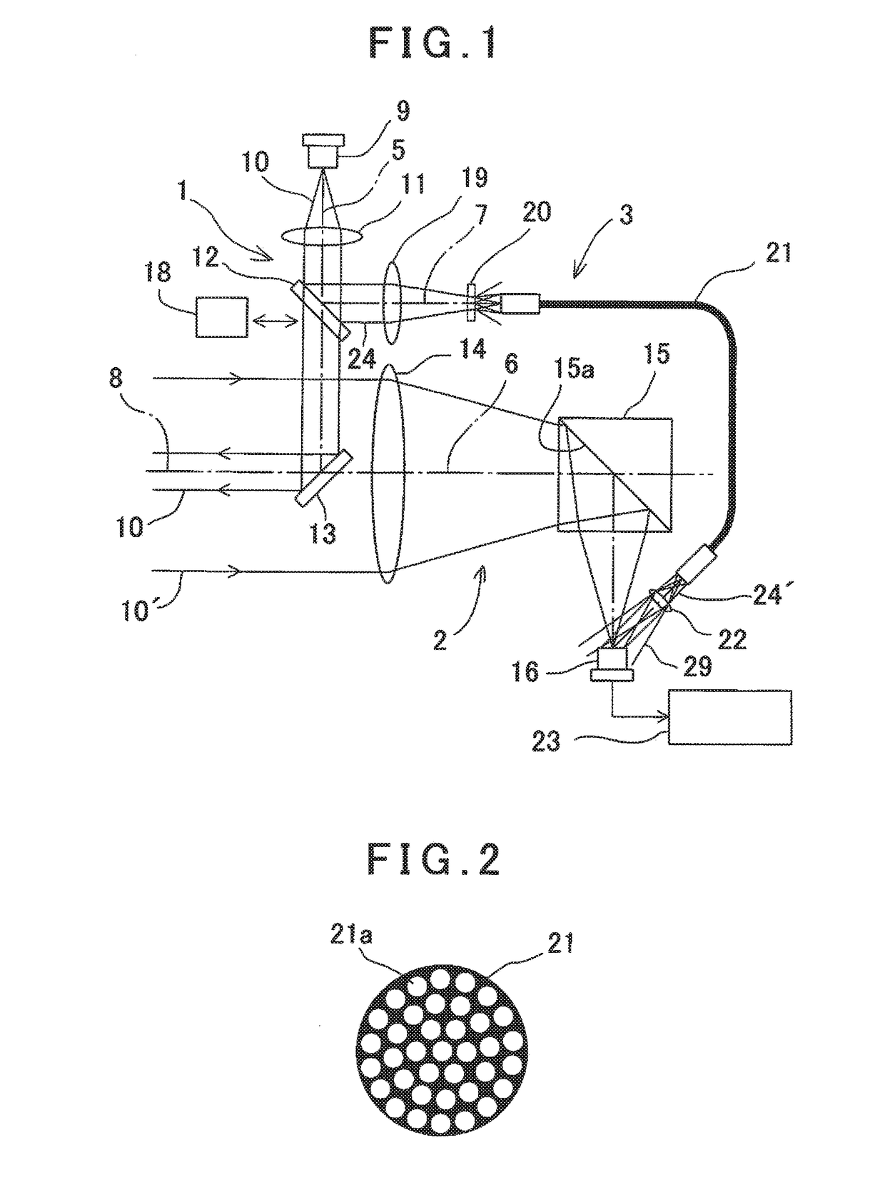
[0029]FIG. 1 shows general features of an optical system of an electro-optical distance meter according to the present invention.

[0030]The optical system mainly has a light projecting optical system 1, a light receiving optical system 2 and an internal reference optical system 3.

[0031]The light projecting optical system 1 has a light projecting optical axis 5, the light receiving optical system 2 has a light receiving optical axis 6 and the internal reference optical system 3 has an internal reference optical axis 7.

[0032]On the light projecting optical axis 5, a light source 9 for emitting a distance measuring light 10 is provided, and further, on the light projecting optical axis 5 toward an object side, a condenser lens 11, a branch mirror 12 and a reflection mirror 13 as a deflection optical member are provided.

[0033]The light projecting optical axis 5 is deflected by the reflection mirror 13, and the light projecting optical axis 5 as deflected becomes a distance measuring opti...

second embodiment

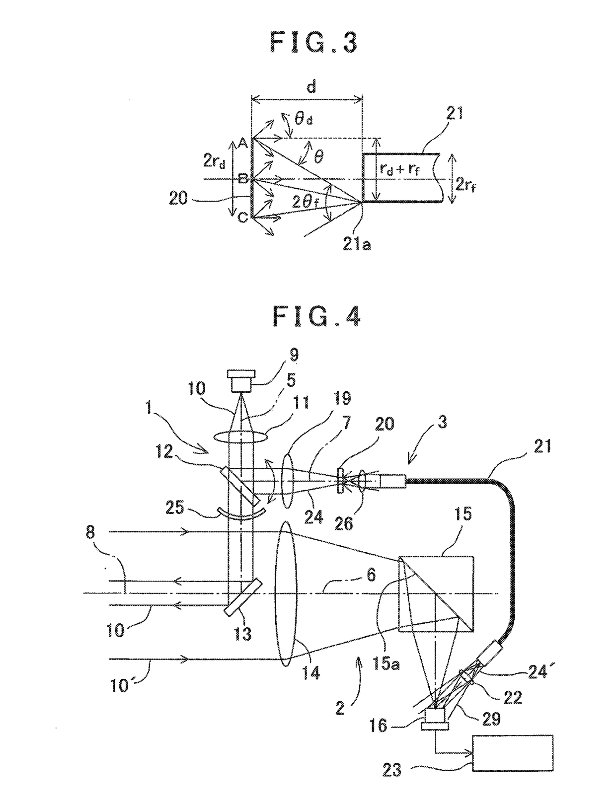
[0069]A description will be given on the present invention by referring to FIG. 4.

[0070]It is to be noted that, in FIG. 4, what are equivalent to components as shown in FIG. 1 are referred by the same symbol, and the detailed description thereof will be omitted.

[0071]In the second embodiment, the branch mirror 12 is fixed and is designed as a half mirror for reflecting a part of a distance measuring light 10 as an internal reference light 24 and for transmitting a remaining part as a distance measuring light 10. Further, a reflectance of the branch mirror 12 is set so as to reflect an appropriate light intensity by which the photodetector 16 is not saturated.

[0072]A shutter 25 is provided as an optical path switching means, and the shutter 25 is constituted so as to move between a light projecting optical axis 5 and an internal reference optical axis 7 and to alternatively shut off the distance measuring light 10 and the internal reference light 24.

[0073]A condenser lens 26 is provi...

third embodiment

[0079]FIG. 6 shows a

[0080]A light attenuation filter 27 is provided on an incident side or an emitting side (the incident side in the figure) of a scattering plate 20.

[0081]The light attenuation filter 27 is designed in a disk-like shape and is rotatable around a support shaft 28. The light attenuation filter 27 is formed so that a density (a light attenuation rate) gradually changes in a circumferential direction.

[0082]An internal reference light 24 transmits through a periphery of the attenuation filter 27. Therefore, the internal reference light 24 transmitting the light attenuation filter 27 is configured in such a manner that a light amount is increased / decreased by rotating the light attenuation filter 27 according to a rotating direction.

[0083]Instead of setting and managing a reflectance of the branch mirror 12, it is possible to set an appropriate light intensity by which the photodetector 16 is not saturated by selecting a rotational position of the light attenuation filte...


PUM


Abstract

An electro-optical distance meter comprises a light source for emitting a distance measuring light, a distance measuring optical system for leading a distance measuring light to a photodetector, an internal reference optical system for leading a part of the distance measuring light as an internal reference light to the photodetector, and an arithmetic processing unit for performing a distance measurement based on light receiving results of the distance measuring light and the internal reference light, wherein the internal reference optical system comprises a condenser lens, a scattering plate for scattering the internal reference light and for forming a secondary light source, and an optical fiber for leading the internal reference light to the photodetector and the internal reference optical system is constituted in such a manner that a light component of the internal reference light emitted from an arbitrary point within a whole surface of the secondary light source enters the optical fiber.

Description

BACKGROUND OF THE INVENTION[0001]The present invention relates to an electro-optical distance meter which projects a distance measuring light to an object to be measured, receives a reflected distance measuring light from the object to be measured and measures a distance to the object to be measured based on a light receiving result.[0002]The electro-optical distance meter projects the distance measuring light emitted from a light emitting element to the object to be measured through a distance measuring optical system, receives a distance measuring reflection light from the object to be measured by a photodetector through the distance measuring optical system and measures a distance to the object to be measured based on a time difference between a light emitting timing of the distance measuring light and a light receiving timing of the distance measuring reflection light.[0003]Further, since a drift caused by a temperature change or the like occurs in a light emitting circuit, a li...

Claims


Application Information

Patent Timeline
IPC IPC(8): G01S7/491G01S17/32G01S7/481G01S7/4913G01S17/10
CPCG01S7/4913G01S7/4818G01S17/32G01S17/10G01S7/497
Inventor SUGIURA, AKINOBUOHISHI, MASAHIRO
Owner KK TOPCON
Why Eureka
Try Eureka