Distance image acquisition apparatus and distance image acquisition method

a technology of distance image acquisition and acquisition method, which is applied in the direction of distance measurement, exposure control, instruments, etc., can solve the problems of omitting rather deteriorating distance measurement accuracy, so as to increase distance measurement accuracy and avoid wasteful imaging or calculation

Active Publication Date: 2018-01-11
FUJIFILM CORP
View PDF0 Cites 31 Cited by
  • Summary
  • Abstract
  • Description
  • Claims
  • Application Information

AI Technical Summary

Benefits of technology

[0041]According to the invention, since exposure control and calculation processing are performed in a drive mode set according to the presence or absence of the influence of ambient light and / or the presence or absence of the influence of the reflectance of the subject from among a plurality of drive modes having different number of times of imaging or different exposure contents, it is possible to increase distance measurement accuracy and to omit wasteful imaging or calculation.

Problems solved by technology

That is, in the distance image acquisition apparatus described in JP2008-145386A, since output data of the first pixel group of the distance image sensor is subtracted from output data of the second pixel group of the distance image sensor, shot noise caused by the subtraction processing is superimposed on the subtracted output data, and for example, in a case of an imaging environment in which ambient light is not exposed, there is a problem in that distance measurement accuracy is rather deteriorated due to processing for eliminating the influence of ambient light.
In this case, it is not possible to completely eliminate the influence of ambient light.
A method is known in which, a general distance image sensor having sensitivity to infrared light is used instead of the special distance image sensor described in JP2008-145386A, imaging with pulse light of infrared light being emitted and imaging with pulse light being not emitted are performed, and a distance image with the influence of ambient light eliminated is acquired based on a differential image between images acquired by the two times of imaging; however, in this case, noise caused by each of the two times of imaging is superimposed on the differential image, and there is a problem that distance measurement accuracy is deteriorated.

Method used


Image

  • Distance image acquisition apparatus and distance image acquisition method
  • Distance image acquisition apparatus and distance image acquisition method
  • Distance image acquisition apparatus and distance image acquisition method

Examples


first embodiment

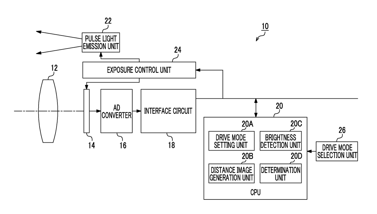
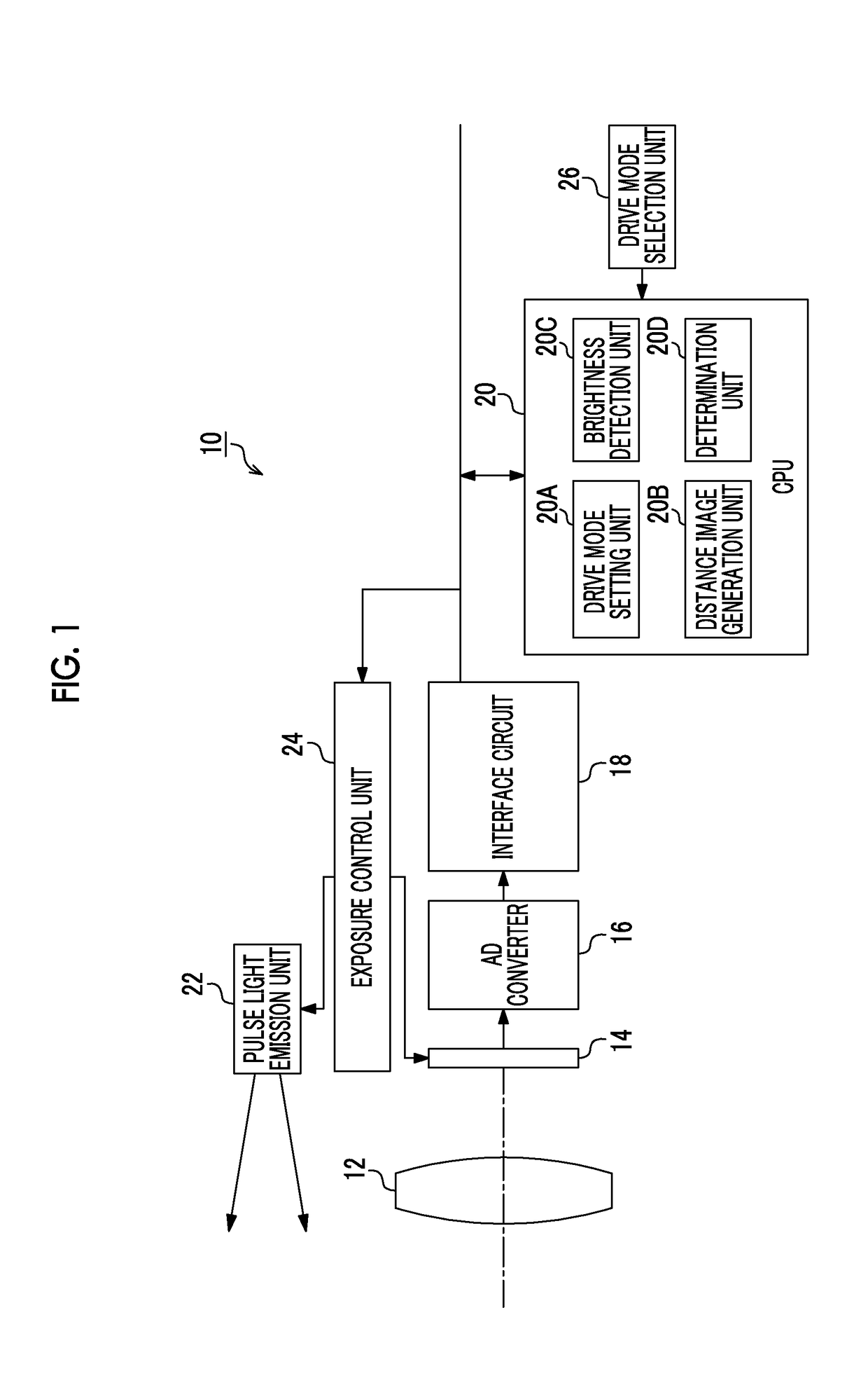
[0082]Hereinafter, a drive mode in a pulse light detection system of a first embodiment will be described.

[0083]

[0084]FIGS. 4A to 4D are diagrams showing exposure control and calculation processing of a first drive mode in the pulse light detection system of the first embodiment.

[0085]The first drive mode is a mode which is set in a case of an imaging environment, in which there is the influence of ambient light and the reflectance of the subject.

[0086]In the first drive mode, as shown in FIGS. 4A, 4B, and 4C, three times of exposure control of the first exposure control, the second exposure control, and the third exposure control are performed.

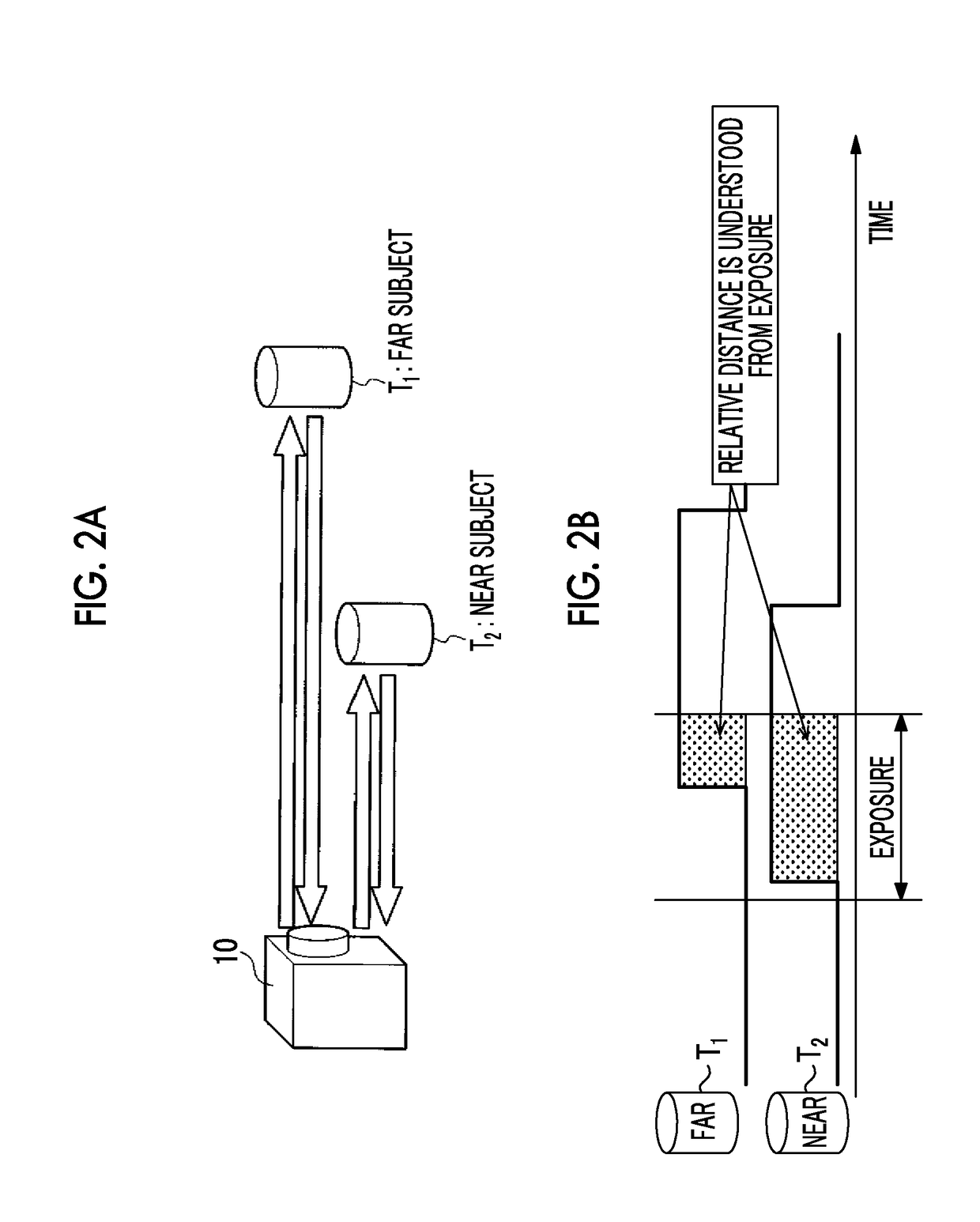
[0087]The first exposure control shown in FIG. 4A is exposure control in which pulse light is emitted from the pulse light emission unit 22, and the exposure period is controlled such that the difference in the exposure between the corresponding light receiving elements of the distance image sensor 14 is generated according to at least the di...

second embodiment

[0117]Next, a drive mode in a pulse light detection system of a second embodiment will be described.

[0118]As described below in detail, the pulse light detection system of the second embodiment is different from the pulse light detection system of the first embodiment in terms of exposure control and calculation processing in the first drive mode and the second drive mode.

[0119]

[0120]FIGS. 8A to 8D are diagrams showing exposure control and calculation processing of a first drive mode in the pulse light detection system of the second embodiment.

[0121]The first drive mode is a mode which is set in a case of an imaging environment, in which there is the influence of ambient light and the reflectance of the subject.

[0122]In the first drive mode, as shown in FIGS. 8A, 8B, and 8C, the first exposure control, the second exposure control, and the third exposure control are performed.

[0123]The first exposure control shown in FIG. 8A is exposure control in which pulse light is emitted from th...


PUM


Abstract

Disclosed are a distance image acquisition apparatus and a distance image acquisition method capable of achieving high distance measurement accuracy and omitting wasteful imaging or calculation. The distance image acquisition apparatus (10) includes a distance image sensor (14), a drive mode setting unit (20A), a distance image generation unit (20B), a pulse light emission unit (22), and an exposure control unit (24). The exposure control unit (24) controls emission and non-emission of pulse light emitted from the pulse light emission unit (22) according to a drive mode set by the drive mode setting unit (20A), and controls exposure in the distance image sensor (14). The distance image generation unit (20B) performs calculation processing of a sensor output acquired from the distance image sensor (14) according to the drive mode set by the drive mode setting unit (20A) to generate a distance image corresponding to a distance of a subject.

Description

CROSS-REFERENCE TO RELATED APPLICATIONS[0001]The present application is a Continuation of PCT International Application No. PCT / JP2015 / 080579 filed on Oct. 29, 2015 claiming priority under 35 U.S.C §119(a) to Japanese Patent Application No. 2015-064773 filed on Mar. 26, 2015. Each of the above applications is hereby expressly incorporated by reference, in their entirety, into the present application.BACKGROUND OF THE INVENTION1. Field of the Invention[0002]The present invention relates to a distance image acquisition apparatus and a distance image acquisition method, and in particular, to a technique for acquiring a distance image using a time of flight (TOF) system.2. Description of the Related Art[0003]A TOF system is a system which irradiates a subject with light and obtains a distance to the subject by measuring a time until reflected light is received by a sensor. A system (hereinafter, referred to as a “pulse light detection system”) which irradiates the subject with pulse lig...

Claims


Application Information

Patent Timeline
Patent Type & Authority Applications(United States)
IPC IPC(8): G01S17/32G01S7/486G01S7/487G01S17/89G01S7/4865G01S17/10G01S17/894
CPCG01S17/32G01S7/487G01S17/89G01S7/4865G01C3/06G01S17/10G03B7/083G01S7/4868G01S17/894H04N23/667H04N23/73H04N23/74H04N25/702
Inventor MASUDA, TOMONORIKAWAI, TOMOYUKI
Owner FUJIFILM CORP
Why Eureka
Try Eureka