Liquid ejection head and liquid ejection apparatus
- Summary
- Abstract
- Description
- Claims
- Application Information
AI Technical Summary
Benefits of technology
Problems solved by technology
Method used
Image
Examples
first embodiment
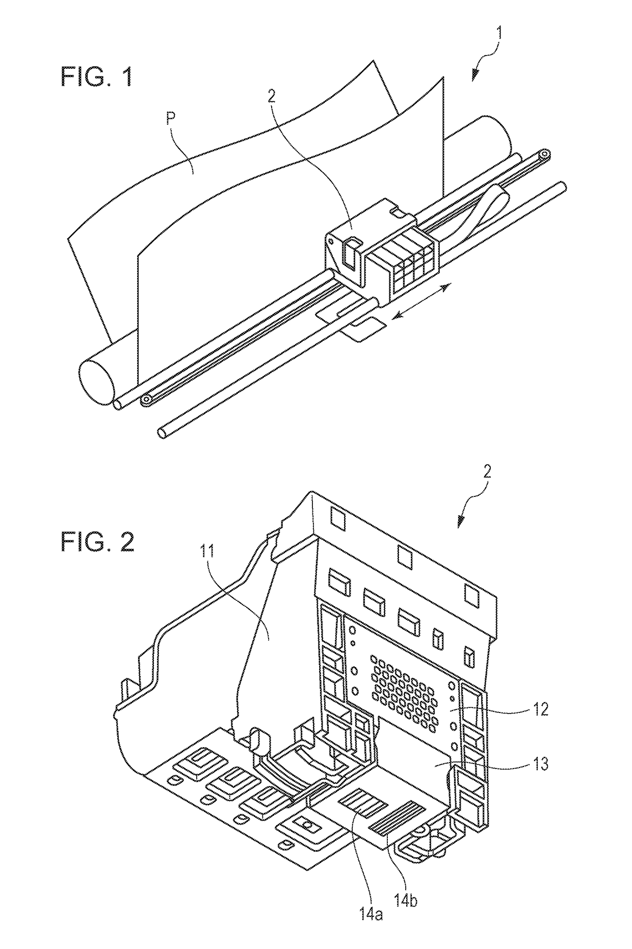
[0027]FIG. 1 is a perspective view schematically illustrating a main part of a liquid ejection apparatus in accordance with a first embodiment of the disclosure. A liquid ejection apparatus 1 illustrated in FIG. 1 is an inkjet recording apparatus which ejects ink as a liquid onto a recording medium P and records an image on the recording medium P. However, the disclosure is not limited to the inkjet recording apparatus but may be applicable to common liquid ejection apparatuses which eject liquids.
[0028]The liquid ejection apparatus 1 illustrated in FIG. 1 includes a liquid ejection head 2 which ejects a liquid. The liquid ejection head 2 is installed so that a surface from which a liquid is ejected faces the recording medium P. The liquid ejection apparatus 1 makes the liquid ejection head 2 eject the liquid while making the liquid ejection head 2 reciprocate in a direction depicted by an arrow in FIG. 1. With the ejection of the liquid, the liquid ejection apparatus 1 makes the re...
second embodiment
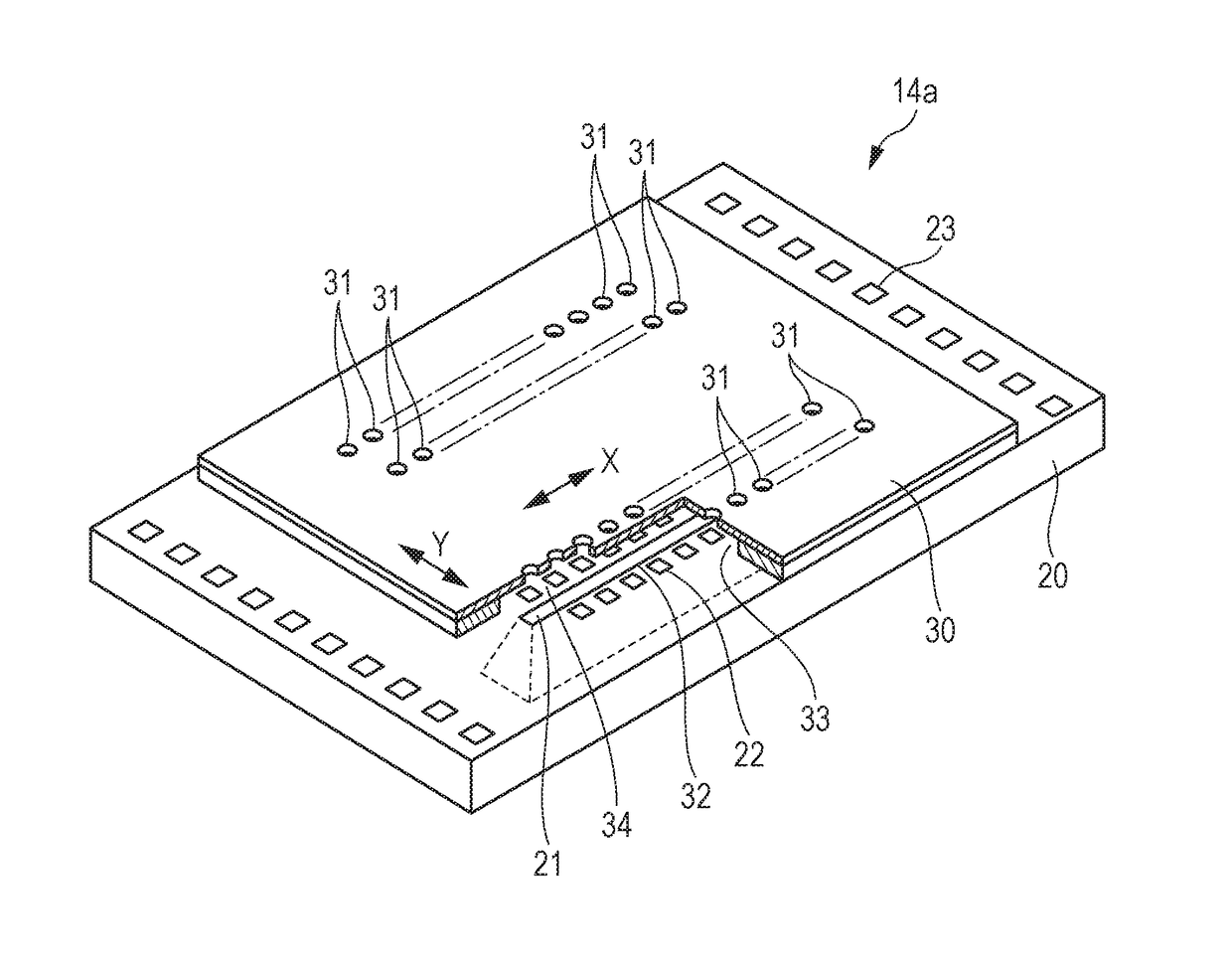
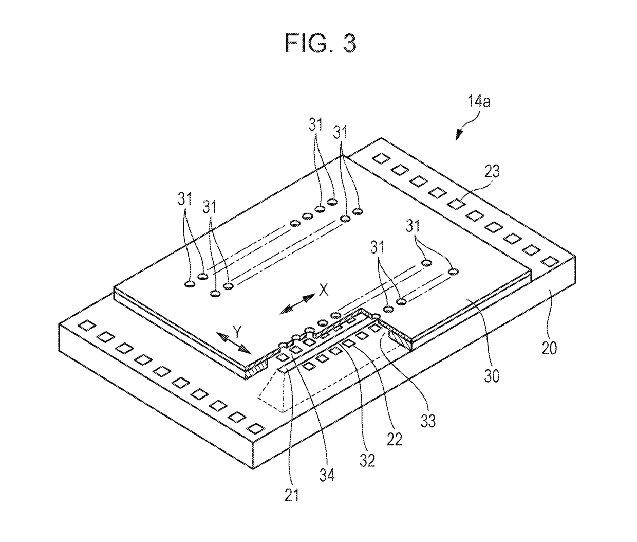
[0053]FIG. 8 is a top view schematically illustrating a print element board 14a in accordance with a second embodiment of the disclosure, and FIG. 9 is a top view schematically illustrating a substrate 20 in accordance with the second embodiment of the disclosure. In an example illustrated in FIGS. 8 and 9, a substrate width CW2 which is a width of the print element board 14a (the substrate 20) is 6.9 mm, and a substrate length CL2 which is a length of the print element board 14a (the substrate 20) is 15 mm. A thickness of the substrate 20 and a thickness of an ejection port forming member 30 are the same as those of the first embodiment.
[0054]Inlets 21a to 21e are formed on the substrate 20 as the inlets 21. The inlets 21a to 21e are formed along one side of the substrate 20, and are provided from one side of the substrate 20 in the order of the inlet 21a, the inlet 21b, the inlet 21c, the inlet 21d, and the inlet 21e. Heater arrays 25a1 to 25e2 consisting of a plurality of heaters...
third embodiment
[0065]FIG. 11 is a top view schematically illustrating a print element board 14a in accordance with a third embodiment of the disclosure, and FIG. 12 is a top view schematically illustrating a substrate 20 in accordance with the third embodiment of the disclosure. In an example illustrated in FIGS. 11 and 12, a substrate width CW3 which is a width of the print element board 14a (the substrate 20) is 10.4 mm, and a substrate length CL3 which is a length of the print element board 14a (the substrate 20) is 15 mm. A thickness of the substrate 20 and a thickness of an ejection port forming member 30 are the same as those of the first embodiment.
[0066]Inlets 21a to 21h are formed on the substrate 20 as the inlets 21. The inlets 21a to 21h are formed along one side of the substrate 20, and are provided from one side of the substrate 20 in the order of the inlet 21a, the inlet 21b, the inlet 21c, the inlet 21d, the inlet 21e, the inlet 21f, the inlet 21g, and the inlet 21h. Heater arrays 2...
PUM
 Abstract
Description
Claims
Application Information
 - R&D
- Intellectual Property
- Life Sciences
- Materials
- Tech Scout
- Unparalleled Data Quality
- Higher Quality Content
- 60% Fewer Hallucinations
Browse by: Latest US Patents, China's latest patents, Technical Efficacy Thesaurus, Application Domain, Technology Topic, Popular Technical Reports.
© 2025 PatSnap. All rights reserved.Legal|Privacy policy|Modern Slavery Act Transparency Statement|Sitemap|About US| Contact US: help@patsnap.com


