Sputtering target and method for finishing surface of such target

a technology of sputtering target and target surface, which is applied in the direction of electrolysis components, vacuum evaporation coatings, coatings, etc., can solve the problems of unstable uniformity of deposition, easy peeling of redeposited film, contaminating substrate, etc., and achieve superior deposition characteristics, superior film evenness, and superior

Active Publication Date: 2011-05-31
JX NIPPON MINING & METALS CORP
View PDF11 Cites 19 Cited by
  • Summary
  • Abstract
  • Description
  • Claims
  • Application Information

AI Technical Summary

Benefits of technology

[0013]Thus, an object of the present invention is to provide a hollow cathode sputtering target which has superior sputter film evenness (uniformity), generates few arcing and particles, is capable of suppressing the peeling of the redeposited film on the bottom face, and has superior deposition characteristics, as well as a method for stably manufacturing this target.
[0014]In order to achieve the foregoing object, the present inventors discovered that by improving / devising the inner bottom face of the hollow cathode sputtering target, a hollow cathode sputtering target which has superior sputter film evenness (uniformity), generates few arcing and particles, is capable of suppressing the peeling of the redeposited film on the bottom face, and has superior deposition characteristics, as well as a method for stably manufacturing this target, could be obtained.
[0016]The present invention yields a superior effect in that it is able to stably obtain a hollow cathode sputtering target which has superior film evenness (uniformity) from the initial stages of sputtering, generates few arcing and particles, is superior deposition characteristics, and favorable target usability.
[0017]Further, there is another significant effect of being able to considerably reduce the peeling of the redeposited from the inner bottom face of a hollow cathode target which was in particular a problem heretofore.

Problems solved by technology

Ordinarily, a deposition area is formed at the bottom face, and there is a significant problem in that the redeposited film will easily peel in the vicinity of the deposition area, and contaminate the substrate by flying to or dropping on the substrate.
Nevertheless, this kind of technology was applied in a hollow cathode sputtering target to roughen the bottom face of the target so as to prevent the peeling of the deposited material (redeposited film), but was unsuccessful.
Contrarily, at the stage of commencing the sputtering process, the result was such that the uniformity of deposition was unstable, and numerous particles were generated.
Therefore, there was no choice but to use a conventional hollow cathode sputtering target, and there are problems in that the evenness (uniformity) of the film is inferior, arcing and particles are generated, and the quality of the sputtered deposition will deteriorate.

Method used


Image

  • Sputtering target and method for finishing surface of such target
  • Sputtering target and method for finishing surface of such target
  • Sputtering target and method for finishing surface of such target

Examples


example 1

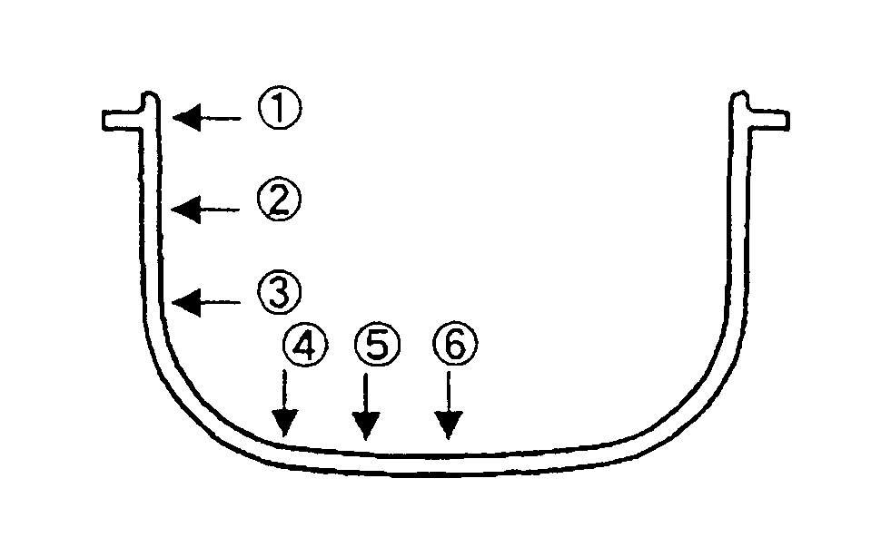
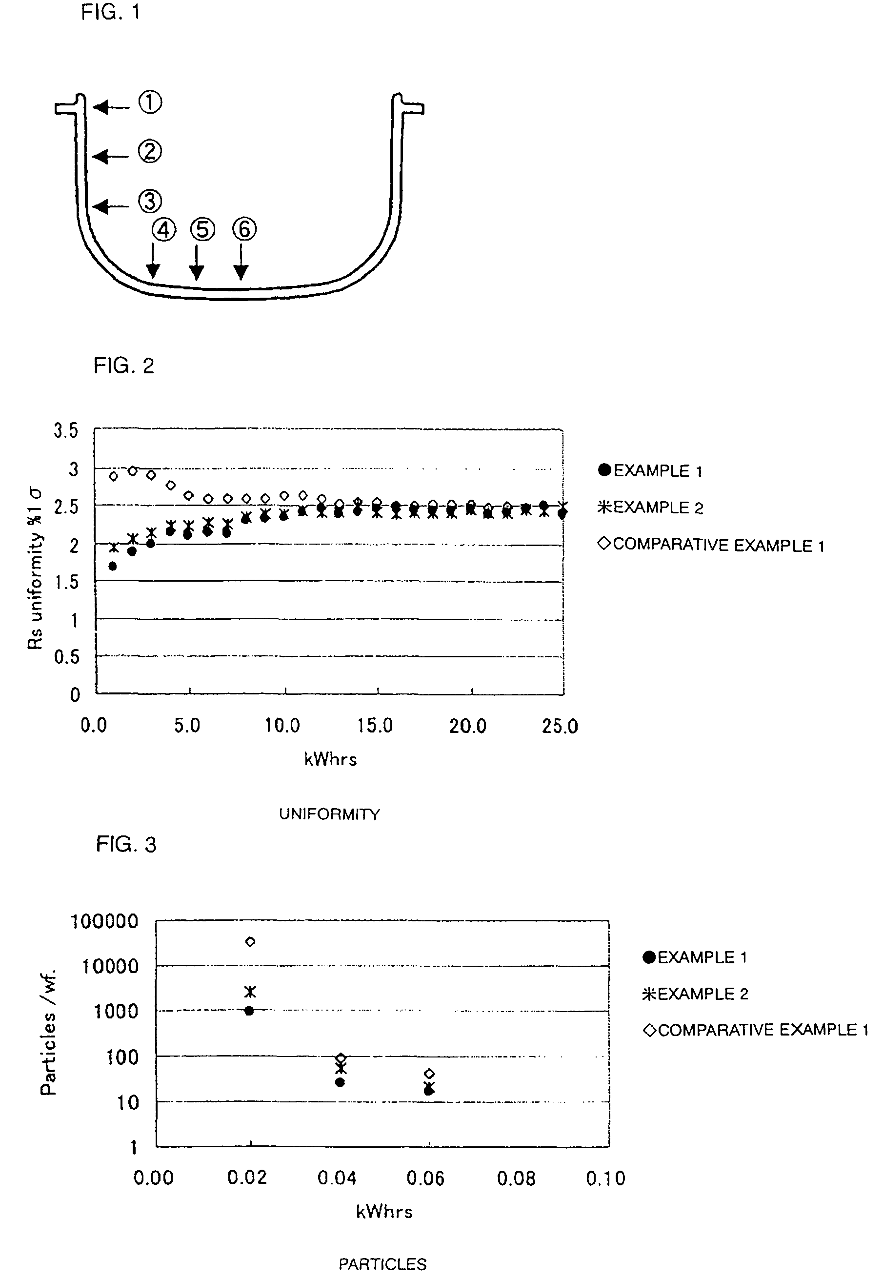
[0031]The inside face of a Ti hollow cathode target was finished by being subject to lathe processing, polishing (sandpapering) and etching. The outline of the obtained hollow cathode sputtering target is shown in FIG. 1. The measurement of the surface roughness of the target was conducted at the respective measurement points (1 to 6) shown in FIG. 1.

[0032]Table 1 shows the surface roughness Ra (μm) of the inside of the target. As shown in Table 1, the surface roughness Ra of the bottom face corresponding to the measurement points 1 to 6 is 0.5% m or less, and the surface roughness Ra of the cylindrical inner peripheral face was also 0.5 μm or less.

[0033]The results upon performing a sputtering test with this hollow cathode target are shown in FIG. 2 and FIG. 3. The uniformity showed favorable values from the initial stage, and there were roughly 900 particles on a single wafer. Further, peeling of the redeposited film of the inner bottom could not be observed up to the expected use...

example 2

[0035]The inside face of a Ti hollow cathode target was finished by being subject to lathe processing, polishing (sandpapering) and etching so as to be Ra (μm)<1.0.

[0036]As with Example 1, the measurement of the surface roughness of the target was conducted at the respective measurement points (1 to 6) shown in FIG. 1. The results are similarly shown in Table 1.

[0037]As shown in Table 1, the surface roughness Ra of the bottom face corresponding to the measurement points 1 to 6 is 1.0 μm or less, and the surface roughness Ra of the cylindrical inner peripheral face was also 1.0 μm or less.

[0038]The results upon performing a sputtering test with this hollow cathode target are shown in FIG. 2 and FIG. 3. As shown in FIG. 2, the uniformity showed favorable values from the initial stage. Also, as shown in FIG. 3, there were roughly 2,500 particles on a single wafer. Further, peeling of the redeposited film at the bottom of the inside face could not be observed up to the expected useful l...

example 3

[0043]The inside face of a Ta hollow cathode target was finished by being subject to lathe processing, polishing (sandpapering) and etching. As with Example 1, the measurement of the surface roughness of the target was conducted at the respective measurement points (1 to 6) shown in FIG. 1.

[0044]The surface roughness Ra (μm) of the inside face of the target is shown in Table 1. As shown in Table 1, the surface roughness Ra at the measurement points 1 to 6 was 0.4 to 0.5 μm.

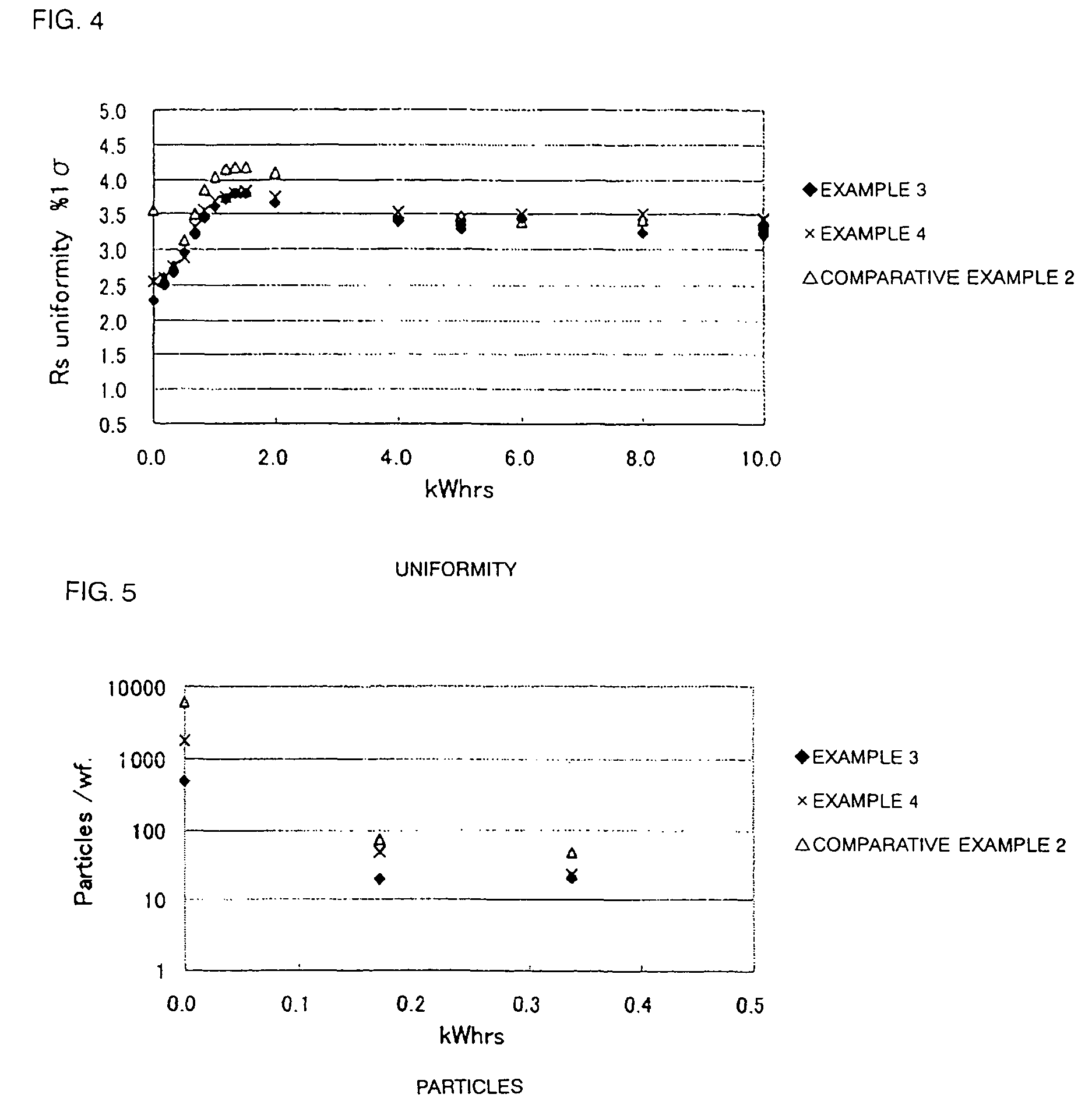
[0045]As a result of performing a sputtering test with this hollow cathode target, as shown in FIG. 4, the uniformity showed favorable values from the initial stage. Also, as shown in FIG. 5, there were roughly 500 particles on a single wafer. Further, peeling of the redeposited film at the bottom of the inside face could not be observed up to the expected useful life.


PUM

PropertyMeasurementUnit
surface roughnessaaaaaaaaaa
Raaaaaaaaaaa

Abstract

Provided is a hollow cathode sputtering target comprising an inner bottom face having a surface roughness of Ra≦1.0 μm, and preferably Ra≦0.5 μm. This hollow cathode sputtering target has superior sputter film evenness (uniformity), generates few arcing and particles, is capable of suppressing the peeling of the redeposited film on the bottom face, and has superior deposition characteristics.

Description

BACKGROUND OF THE INVENTION[0001]The present invention relates to a hollow cathode sputtering target which generates few particles and which has superior surface cleansability, and to a surface finishing method of this target.BACKGROUND ART[0002]In recent years, the sputtering method for forming a film from materials such as metal or ceramics has been used in numerous fields such as electronics, corrosion resistant materials and ornaments, catalysts, as well as in the manufacture of cutting / grinding materials and abrasion resistant materials.[0003]Although the sputtering method itself is a well-known method in the foregoing fields, recently, particularly in the electronics field, a sputtering target suitable for forming films of complex shapes and forming circuits is in demand.[0004]Under these circumstances, a hollow cathode sputtering target has been proposed recently. This target is formed in the shape of a cup, and is referred to as a hollow cathode sputtering target based on su...

Claims


Application Information

Patent Timeline
Patent Type & Authority Patents(United States)
IPC IPC(8): C23C14/06C23C14/34
CPCC23C14/3414C23C14/0682C23C14/08C23C14/14C23C14/54
Inventor TSUKAMOTO, SHIRO
Owner JX NIPPON MINING & METALS CORP
Why Eureka
Try Eureka