
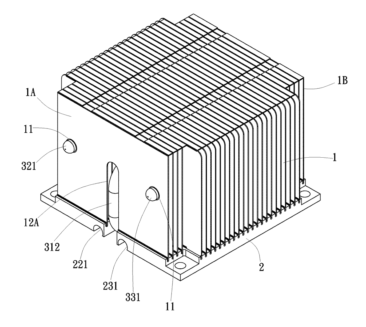
Heat sink assembly

a heat sink and assembly technology, applied in indirect heat exchangers, light and heating devices, etc., can solve the problems of not meeting environmental safety requirements, unable to achieve comprehensive heat absorbing and dissipation effects, and low heat dissipation efficiency of prior aet designs, so as to enhance the overall heat dissipation efficiency of the heat sink assembly and quick dissipation

Active Publication Date: 2018-01-18
HUANG TSUNG HSIEN
View PDF1 Cites 0 Cited by
  • Summary
  • Abstract
  • Description
  • Claims
  • Application Information

AI Technical Summary

Benefits of technology

The solution significantly improves heat dissipation efficiency by evenly distributing heat across the total area of the base block and cooling fins, while eliminating the need for solder bonding and ensuring environmental compliance.

Problems solved by technology

Because heat transfer path is limited to the middle part of the base block and the middle part of the group of cooling fins, these designs cannot achieve comprehensive heat absorbing and dissipating effects.
Therefore, the heat dissipation efficiency of the prior aet designs is low.
These designs need to employ a solder bonding technique to bond the curved heat pipes, the base block and the group of cooling fins together, and therefore these designs do not comply with environmental safety requirements.
Further, because the heat pipes are not exposed to the outside for direct contact with the heat source component, the heat pipes can simply transfer heat indirectly, thus lowering the overall heat dissipation efficiency.

Method used


Image

  • Heat sink assembly
  • Heat sink assembly
  • Heat sink assembly

Examples


first embodiment

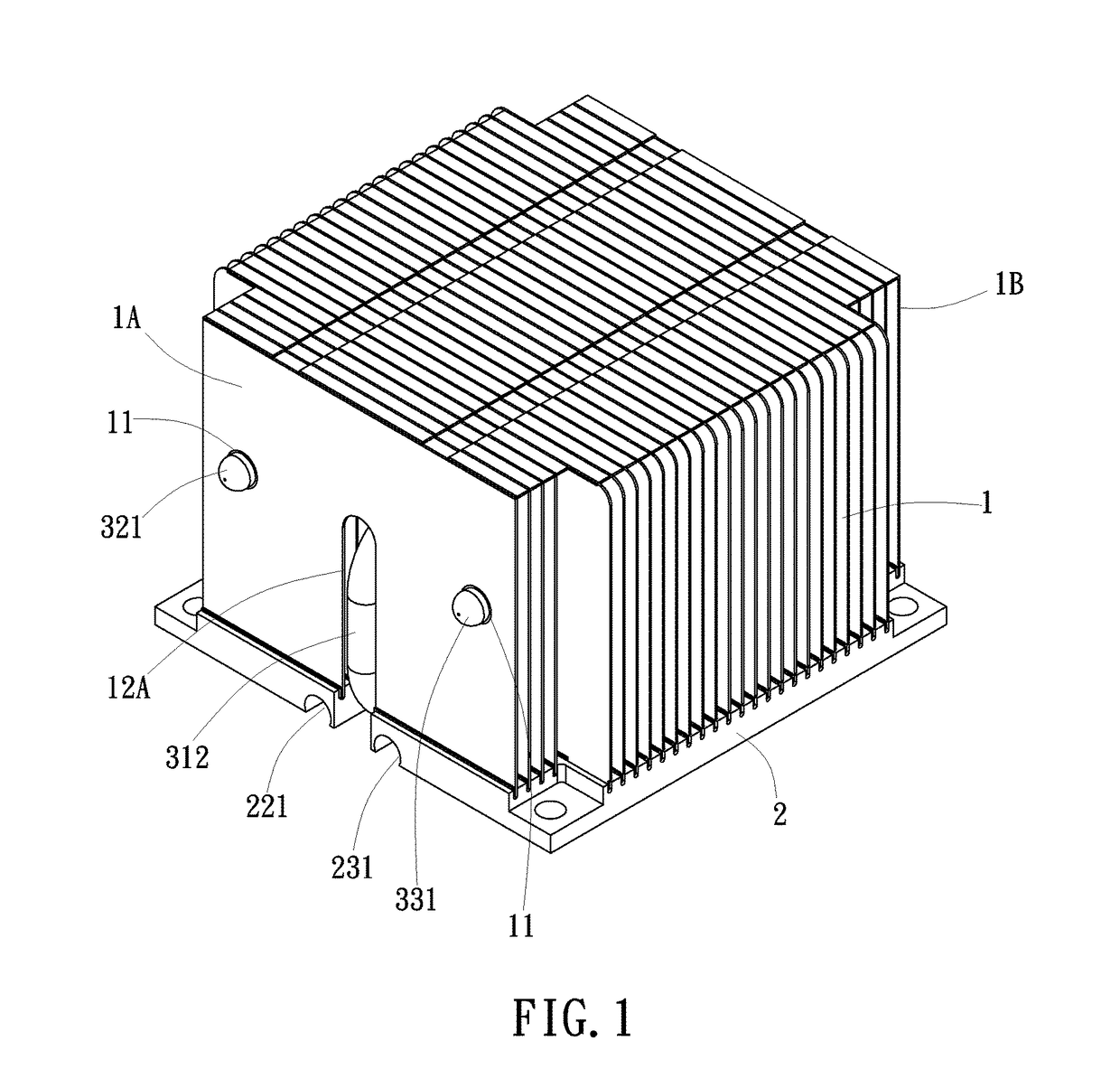
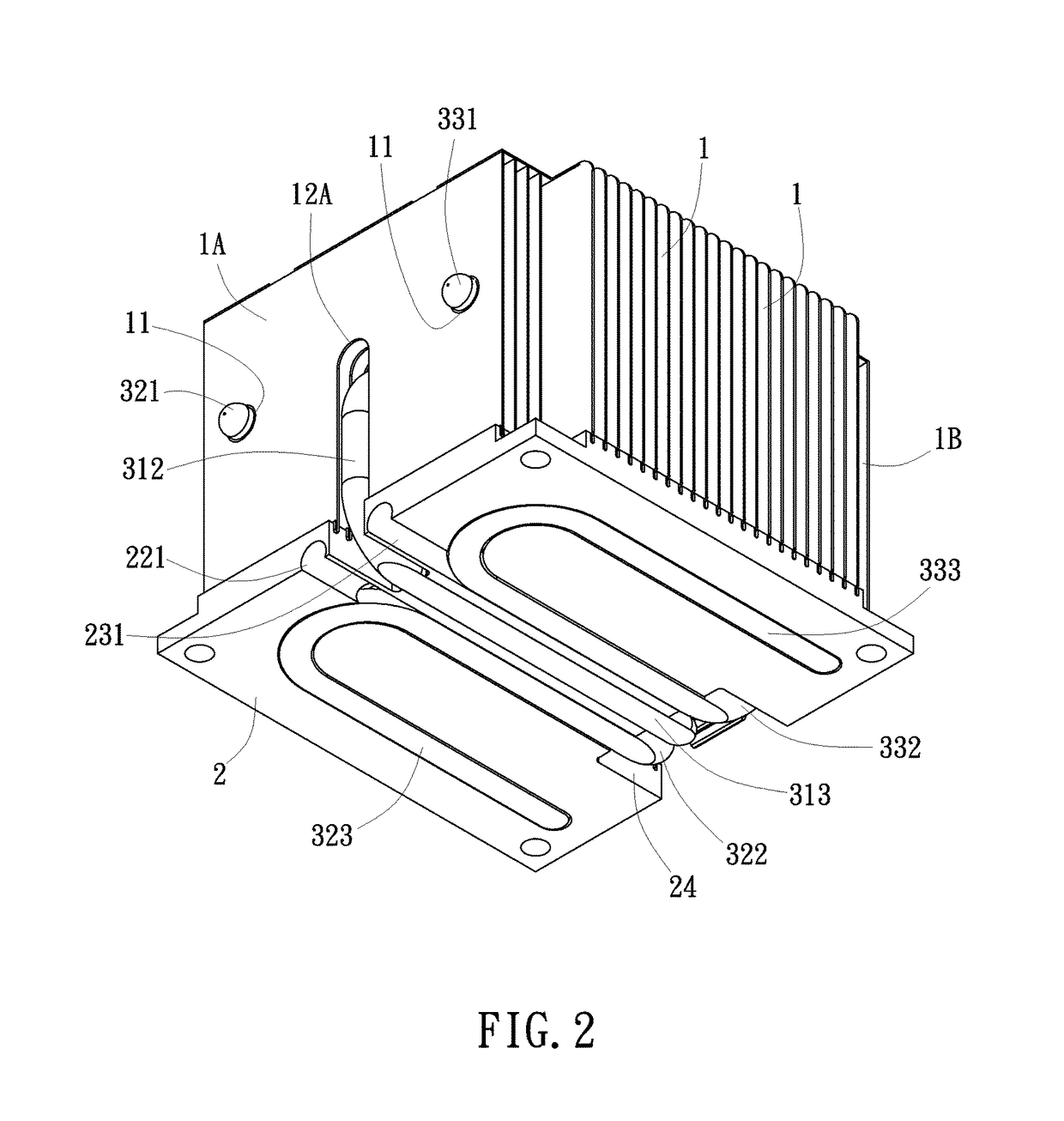
[0022]Referring to FIGS. 1-9, a heat sink assembly in accordance with the present is shown. The heat sink assembly comprises a plurality of cooling fins 1, a base block 2 and at least three heat pipes 31,32,33 (see FIG. 8). The cooling fins 1 are installed in a top wall of the base block 2 (see FIGS. 1-3), each comprising a plurality of tight-fit mounting holes 11 for the mounting of the heat pipes 31,32,33.

[0023]The base block 2, as illustrated in FIG. 9, comprises a straight mounting groove 21 located at a bottom wall thereof and two U-shaped mounting grooves 22,23 symmetrically disposed at two opposite lateral sides relative to the straight mounting groove 21. The straight mounting groove 21 can be located at the midpoint of the bottom wall of the base block 2. The U-shaped mounting grooves 22,23 can be respectively located at two opposite lateral sides of the bottom wall of the base block 2.

[0024]The three heat pipes 31,32,33, as illustrated in FIG. 8, include one U-shaped heat ...

second embodiment

[0034]In this second embodiment, the base block 2a further comprises a spacer portion 25a formed of a part of the bottom wall thereof between the two mating notches 24a,24b, and a plurality of mounting through holes 26a respectively disposed at four corners thereof and opposing front and rear ends of the spacer portion 25a for fastening to a circuit board (not shown) by respective fastening members.

[0035]The mounting arrangement between the cooling fins 1,1′ and the base block 2,2a is achieved using a tight fitting technique that is of the known art and not within the scope of the present invention, therefore, no further detailed description in this regard will be necessary.

[0036]In the heat sink assembly in accordance with the present invention, the cooling fins 1,1′, the base block 2,2a and the three heat pipes 31,32,33 (or four heat pipes 31a,31b,32a,33a) are respectively fastened together using a tight fitting technique, therefore, when thermal expansion occurs, the overall stru...


PUM


Abstract

A heat sink assembly includes a base block having a straight mounting groove on the middle and two U-shaped mounting grooves at two opposite lateral sides, cooling fins installed in the top wall of the base block, each cooling fin having multiple tight-fit mounting holes, a U-shaped heat pipe having a lower segment peripherally press-fitted into the straight mounting groove in flush with the bottom wall of the base block and an upper segment tightly inserted into one respective tight-fit mounting hole of each cooling fin, and two symmetrical, curved heat pipes with respective U-shaped lower segments thereof respectively and peripherally press-fitted into the U-shaped mounting grooves in flush with the bottom wall of the base block and respective upper segments thereof tightly inserted into respective tight-fit mounting holes of each cooling fin. Thus, heat can be drawn upwards from a heat source and evenly distributed through the cooling fins.

Description

CROSS REFERENCE TO RELATED APPLICATIONS[0001]This application is a division of pending U.S. patent application Ser. No. 14 / 988510 filed Jan. 5, 2016, which claims the priority benefit of China Application No. 201510650595.X filed Oct. 9, 2015. The entirety of each of said Applications is incorporated herein by reference.BACKGROUND OF THE INVENTION(a) Field of the Invention[0002]The present invention relates to heat sink technology, and more particularly to a heat sink assembly, which draws heat upwards and then evenly distributes heat to middle and lateral areas of the cooling fins thereof for quick dissipation.(b) Description of the Prior Art[0003]Conventional heat sinks generally comprise a plurality of cooling fins, a base block and at least one heat pipe. Exemplars are seen in Taiwan Patents Number 1260962; 1359254. According to these prior art designs, each heat pipe has one end inserted into the bottom side of the base block and an opposite end coupled to the group of cooling ...

Claims


Application Information

Patent Timeline
Patent Type & Authority Applications(United States)
IPC IPC(8): F28D15/02
CPCF28D15/0275
Inventor HUANG, TSUNG-HSIEN
Owner HUANG TSUNG HSIEN
Learn More