Midsole Structure for a Shoe
a technology of midsole and shoe, which is applied in the field of midsole structure for shoes, can solve problems such as loss of ride feeling during running, and achieve the effects of improving cushioning properties maintaining stability at the time of impacting the ground, and reducing hardness
- Summary
- Abstract
- Description
- Claims
- Application Information
AI Technical Summary
Benefits of technology
Problems solved by technology
Method used
Image
Examples
first alternative embodiment
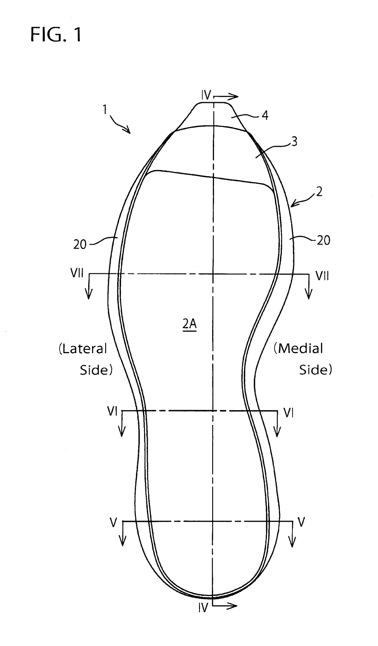
[0061]In the above-mentioned embodiment, an example in which the lower midsole 3 extends longitudinally from the heel region through the tread region to the toe portion (i.e. a full-length type) was shown, but application of the present invention is not limited to such an embodiment. FIGS. 9 to 17 show a first alternative embodiment of the present invention.
[0062]As shown in FIGS. 9 to 12, the lower midsole 3 is disposed at the heel region. The upper midsole 2 extends longitudinally from the heel region through the tread region to the toe portion. That is, in this exemplification, the heel region has a two-layer structure formed of the upper midsole 2 and the lower midsole 3 and the other regions have a single-layer structure of the upper midsole 2. A front end edge portion 3a of the lower midsole 3 may extend to a rear end portion of the plantar arch region and the front end edge portion 3a may have a different shape other than that shown in FIG. 9. At medial and lateral rear end p...
second alternative embodiment
[0071]In the above-mentioned embodiment, an example in which the lower midsole 3 extends longitudinally from the heel region through the tread region to the toe portion (i.e. a full-length type) was shown, but application of the present invention is not limited to such an embodiment. FIGS. 18 to 25 show a second alternative embodiment of the present invention.
[0072]As shown in FIGS. 18 to 21, the lower midsole 3 is disposed at a region extending from the heel region to the plantar arch region. The upper midsole 2 extends longitudinally from the heel region through the tread region to the toe portion. That is, in this exemplification, the heel region and the plantar arch region have a two-layer structure formed of the upper midsole 2 and the lower midsole 3 and the other regions have a single-layer structure of the upper midsole 2. Also, at a region extending from a lateral rear end portion through a medial rear end portion to the medial side of the heel region, an outer circumferent...
third alternative embodiment
[0082]In the above-mentioned embodiment and first and second alternative embodiments, an example in which the midsole structure 1 is formed of two layers of the high-hardness upper midsole 2 and the low-hardness lower midsole 3 was shown, but in the present invention, the midsole structure 1 may be formed of three or more layers of the midsoles.
[0083]The above-mentioned embodiment and respective variants are to be considered in all respects only as illustrative of the present invention and not restrictive. Those skilled in the art to which the invention pertains may make various modifications and other embodiments employing the principles of this invention without departing from its spirit or essential characteristics particularly upon considering the foregoing teachings even when there are no explicit descriptions in this specification.
[0084]In the above-mentioned embodiment, a midsole structure for a running shoe was taken as an example, but application of the present invention is...
PUM
| Property | Measurement | Unit |
|---|---|---|
| hardness | aaaaa | aaaaa |
| thickness | aaaaa | aaaaa |
| structure | aaaaa | aaaaa |
Abstract
Description
Claims
Application Information
 - R&D
- Intellectual Property
- Life Sciences
- Materials
- Tech Scout
- Unparalleled Data Quality
- Higher Quality Content
- 60% Fewer Hallucinations
Browse by: Latest US Patents, China's latest patents, Technical Efficacy Thesaurus, Application Domain, Technology Topic, Popular Technical Reports.
© 2025 PatSnap. All rights reserved.Legal|Privacy policy|Modern Slavery Act Transparency Statement|Sitemap|About US| Contact US: help@patsnap.com


