Fastening element

a technology of fastening elements and components, applied in the direction of superimposed coating process, nails, screws, etc., can solve the problems of high-strength steel, inability to tolerate corrosive action well, and relatively expensive stainless chrome steel, etc., to achieve high resistance

Inactive Publication Date: 2009-03-05
HILTI AG
View PDF3 Cites 3 Cited by
  • Summary
  • Abstract
  • Description
  • Claims
  • Application Information

AI Technical Summary

Benefits of technology

[0010]This and other objects of the present invention, which will become apparent hereinafter, are achieved by providing a fastening element having, in addition to the skin zone which is formed of a first low-carbon austenitic steel with a first alloy metal, a first intermediate zone provided between the core zone and the skin zone and formed of a second low-carbon steel having a smaller hardness than the steel the core zone is formed of. The steel of the core zone is preferably a martensitic or bainitic steel. By providing an intermediate zone formed of a second low-carbon steel that has a different metallurgical composition than the low-carbon steel of the skin zone, there is produced a fastening element having a high resistance against the secondary hydrogen embrittlement and that can be economically produced. The use of the chrome steel can, therefore, be dispensed with.

Problems solved by technology

A high-strength steel, however, does not tolerate a corrosive action well.
Therefore, such fastening elements should be used in dry interior spaces and are not suitable for outside use.
The drawback of these workpieces consists in that the stainless chrome steel is relatively expensive.

Method used


Image

  • Fastening element
  • Fastening element

Examples


Embodiment Construction

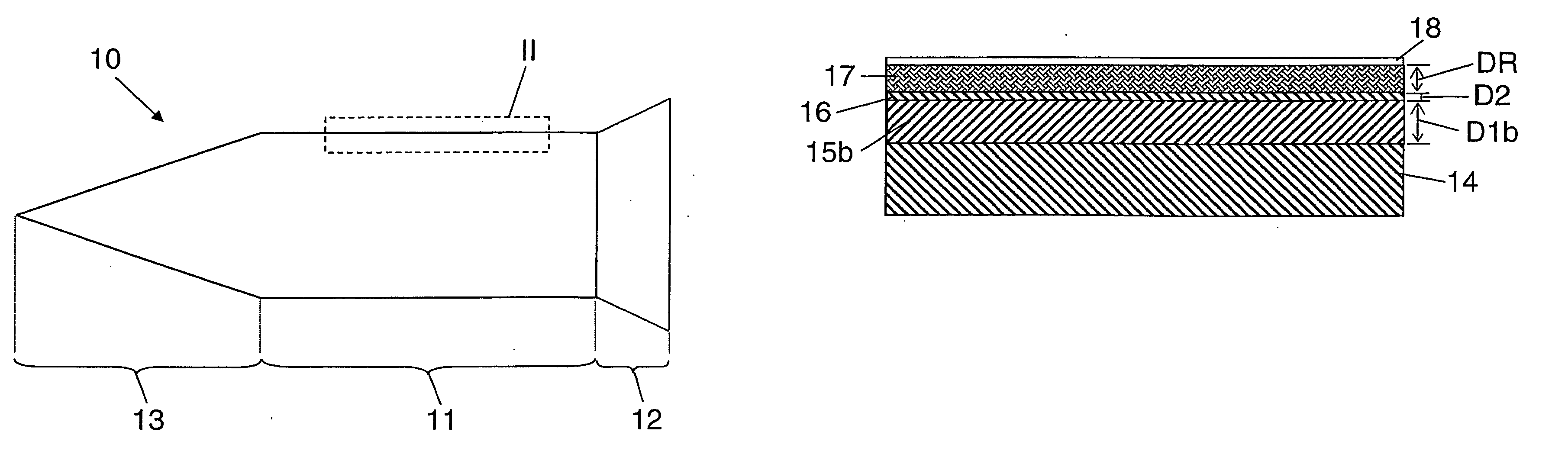
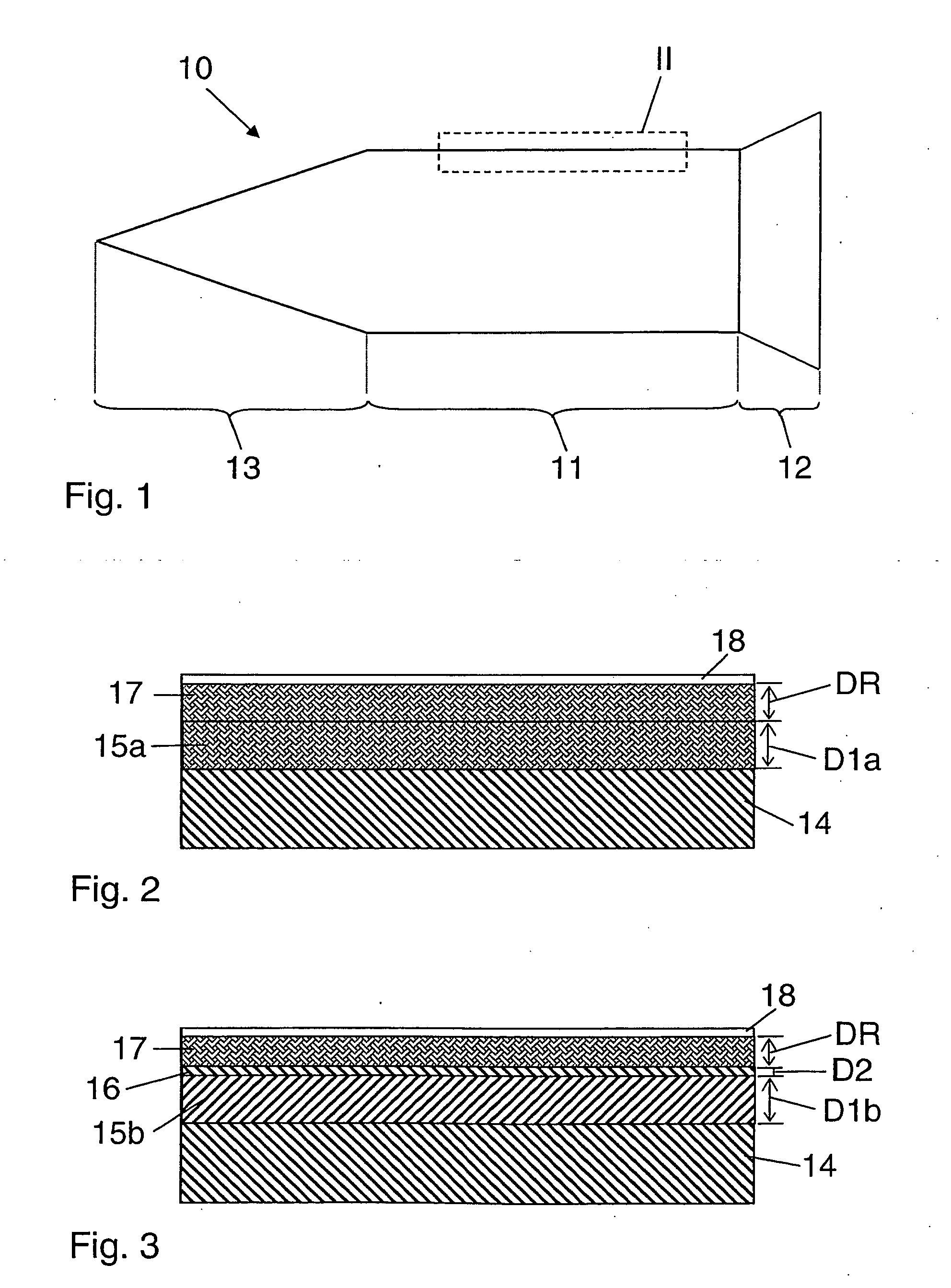
[0026]A fastening element 10 according to the present invention, which is shown in FIGS. 1-2 and is formed as a nail, has a shaft 11, a head 12 provided at one end of the shaft 11, and a pointed tip 13 provided at the shaft other end. The fastening element 10 has, as shown in FIG. 2, a core zone 14 formed of a carbon steel having a martensitic or bainitic structure and a hardness of which lies in a range between about 30 and 62 HRC. At least in one region of the shaft 11, radially outwardly, there is provided a skin zone 17 formed of a first less hardened, low-carbon steel alloyed with a first alloy metal. The skin zone 17 which has, perpendicular to the surface of the core zone 14, a thickness DR in a range from 0.001 mm to 1 mm, has an austenitic structure. As an alloy metal a metal, which is selected from a group containing Ni, Mn, Co, Al, Cr, V or MO, is used. Within the skin zone 17, the concentration of the alloy metal increases from inside out. The austenitic skin zone can be...


PUM

PropertyMeasurementUnit
thicknessaaaaaaaaaa
thicknessaaaaaaaaaa
thicknessaaaaaaaaaa

Abstract

A fastening element has a core zone (14) formed of a relatively hard carbon steel, a skin zone (17) located outwardly of the core zone (14) and formed of a first low-carbon austenitic steel alloyed with a first alloy metal, and an intermediate zone (15a, 15b) provided between the core zone (14) and the skin zone (17) and formed of a second low-carbon steel having a smaller hardness than the steel the core zone (14) is formed of.

Description

BACKGROUND OF THE INVENTION[0001]1. Field of the Invention[0002]The present invention relates to a fastening element having a core zone formed of a relatively hard carbon steel and a skin zone located outwardly of the core zone and formed of a low-carbon austenitic steel alloyed with a first alloy metal.[0003]2. Description of the Prior Art[0004]The fastening element of the type described above such as, e.g., nails, bolts, screws, anchors, and the like are formed of steel, in particular of a high-strength steel, and are used in an attachment technology for securing objects to hard receiving materials such as concrete, metal, stone or for connecting the objects with each other. The fastening elements have a shaft with, if needed, a pointed end and, if needed, a head provided at the opposite end and having an increased, in comparison with the shaft, diameter. The driving of the fastening element or the attachment process is carried out, e.g., by applying blows to the fastening element...

Claims


Application Information

Patent Timeline
Patent Type & Authority Applications(United States)
IPC IPC(8): F16B19/14
CPCB32B15/011C21D9/0093C23C26/00Y10S411/901F16B19/14C23C28/021Y10S411/914C23C28/023B32B15/01C23C28/00
Inventor FELDER, GERALDBIER, CARMEN
Owner HILTI AG
Why Eureka
Try Eureka