Supercharge Your Innovation With Domain-Expert AI Agents!

Method and apparatus for sequential injection moulding of plastic materials

a technology of plastic materials and injection moulding, applied in the direction of coatings, etc., can solve the problems of generating weld lines that form, affecting the structural stability of the article, and normally being inacceptable for the required aesthetic standards, etc., and achieve the effect of efficient overcom

Active Publication Date: 2018-02-01
INGLASS SPA
View PDF0 Cites 0 Cited by
  • Summary
  • Abstract
  • Description
  • Claims
  • Application Information

AI Technical Summary

Benefits of technology

The invention proposes a method of creating flow fronts to adjust the shape of a weld line in plastic materials injected by different injectors. This can improve aesthetics and make the weld line regular and straight, preferably directed transversely to the molded article. The position of the weld line can be adjusted, making it easier to position in areas that do not require high aesthetic parameters. This method reduces the thickness of the molded article and avoids defects such as pressure lines.

Problems solved by technology

One of the defects arising from sequential injection lies in the generation of weld lines that form as a result of the collision between the plastic material fronts coming from different injectors, and thus different directions.
These weld lines are normally unacceptable for the required aesthetic standards, also due to an irregular profile that is observed on the surface of the moulded article, not only from an aesthetic point of view but also in that the structural stability of the article could be jeopardised due to the fact that such weld lines represent vulnerable points.
However, total elimination is very difficult to obtain without entailing considerable complications in the injection system or other types of drawbacks on the moulded article.
This solution entails considerable drawbacks due to the installation complication of a film injection, as well as the increase of the thickness of the final article due to the superimposition of the two flows.
In addition, the instantaneous and complete opening of the lateral injectors can leave defects such as pressure lines on the material already coming from the central injector.
A moulding apparatus thus made is obviously difficult to obtain, given that there is provided for the supply of two different materials for the same system, and it does not overcome the problem related to the considerable thickness of the final article.

Method used


Image

  • Method and apparatus for sequential  injection moulding of plastic materials
  • Method and apparatus for sequential  injection moulding of plastic materials
  • Method and apparatus for sequential  injection moulding of plastic materials

Examples


Embodiment Construction

[0027]The following detailed description refers to a specific embodiment of the invention, in particular regarding the moulding of a spoiler for motor vehicles, which shall however not be deemed limiting in any manner whatsoever. The invention applies to sequential injection moulding apparatus of any type as well as the production of any article that requires sequential injection.

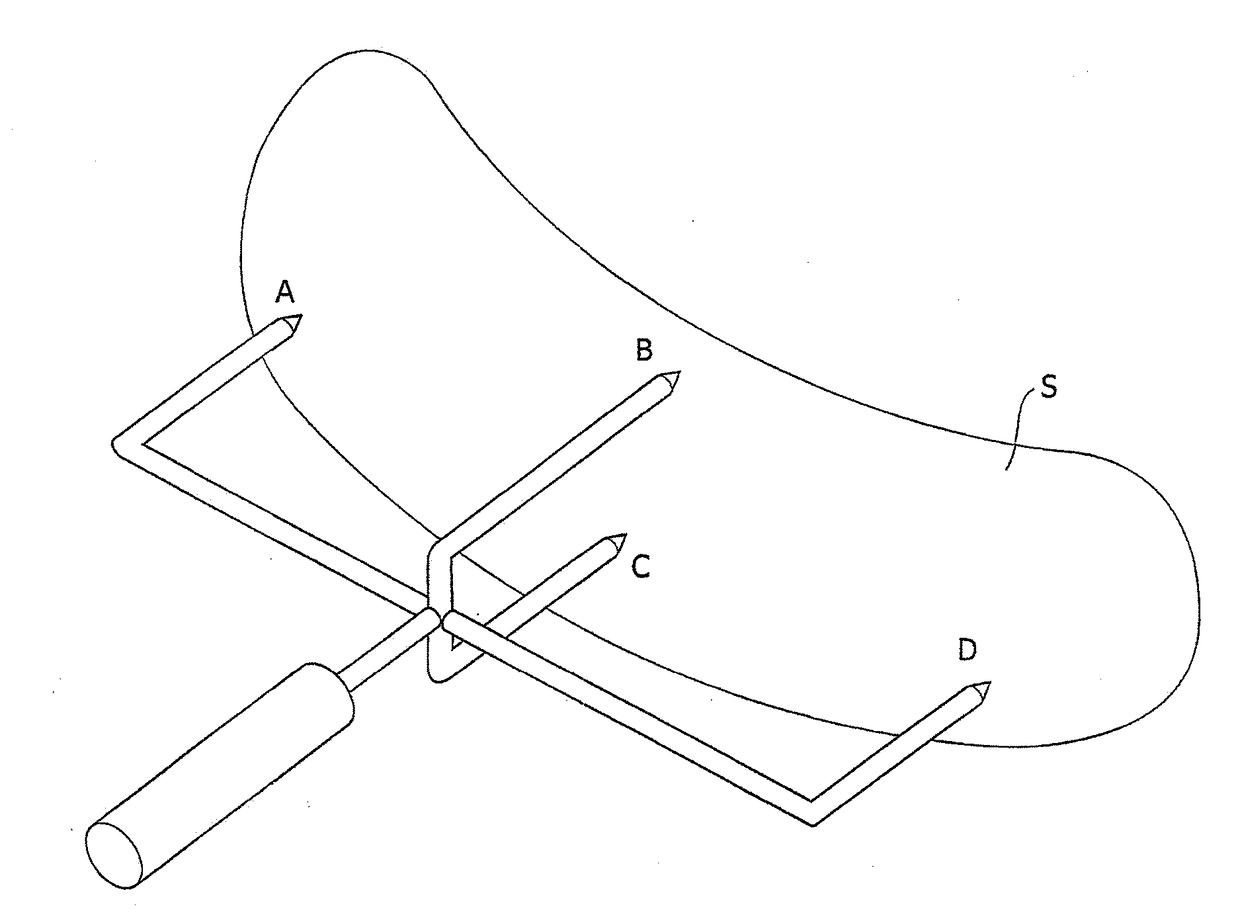
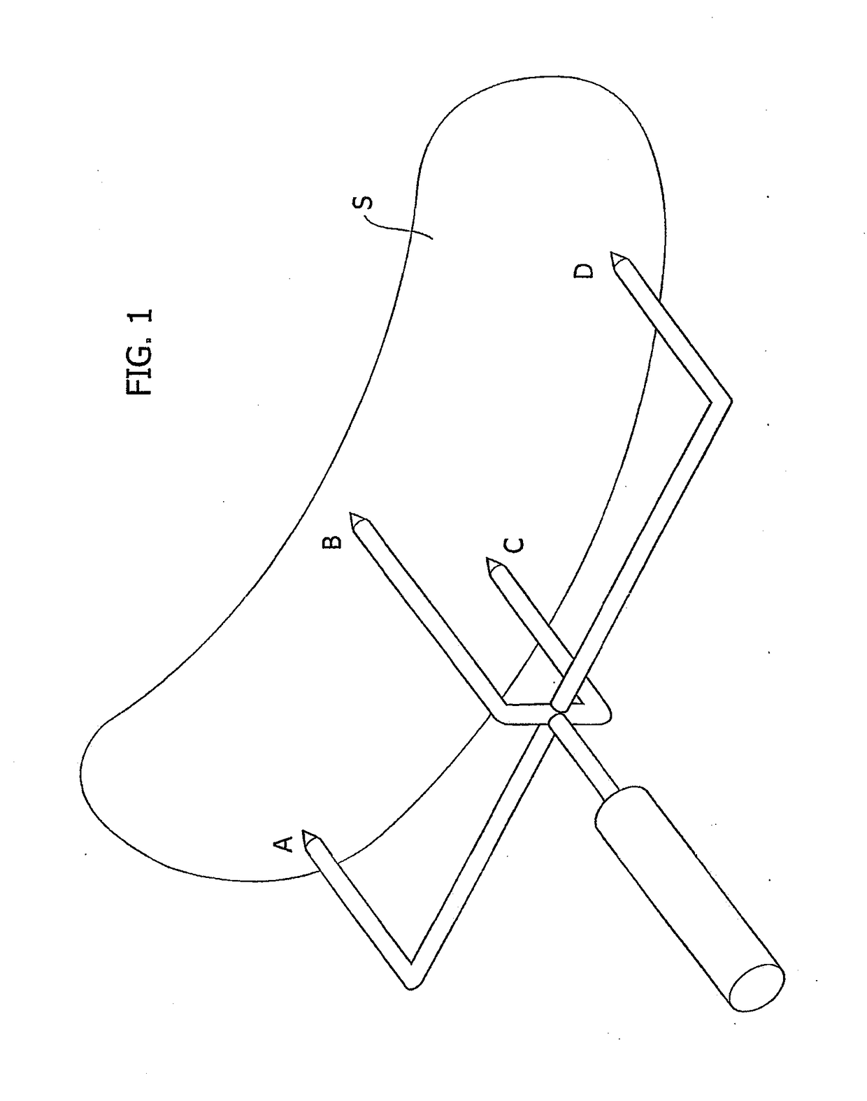
[0028]FIG. 1 schematically shows the spoiler S, or the mould cavity for the forming thereof, and it entirely generally and essentially represents a sequential injection moulding apparatus for the forming thereof. In this schematisation, the apparatus comprises four injection points respectively provided at the central area (B, C) of the spoiler S, and at the end areas (A, D) thereof.

[0029]The injection points A, B, C, D consist, in an entirely conventional manner (for example as described and illustrated in US-2015 / 0266216 on behalf of the Applicant, in injectors comprising a nozzle and a valve pin displace...


PUM

PropertyMeasurementUnit
Shapeaaaaaaaaaa

Abstract

A method and apparatus for the sequential injection moulding of plastic material into the mould cavity or by using a plurality of controlled open-close injectors, wherein the sequentially injected plastic material originates in mould flow fronts in different directions whose collision generates at least one weld line on the moulded article. The sequential injection is actuated with specific modes according to which the opening of the at least one of said injectors is anticipated or delayed with respect to other injectors and / or at least one of the injectors is closed partly and / or at least one of the injectors is gradually opened only partly. Such specific modes are managed to control and define the shape and / or the position of the weld line on the moulded article.

Description

FIELD OF THE INVENTION[0001]The present invention regards a method and apparatus for the sequential injection moulding of plastic material.[0002]Sequential injection finds particular application in the moulding of large components for example in the automotive industry (bumpers, spoilers etc.) which requires particularly high-quality level, both from a structural and aesthetic point of view.[0003]Sequential injection provides for the use of a plurality of controlled close-open injectors arranged along the mould cavity, and comprises a filling phase in which said injectors are opened according to a pre-set sequence to progressively fill the mould cavity and a subsequent phase for packing the plastic material injected into the mould cavity.[0004]One of the defects arising from sequential injection lies in the generation of weld lines that form as a result of the collision between the plastic material fronts coming from different injectors, and thus different directions. These weld lin...

Claims


Application Information

Patent Timeline
IPC IPC(8): B29C45/76B29C45/00B29C45/13
CPCB29C45/762B29C45/7613B29C45/13B29C2945/76859B29C2045/0032B29C2945/76648B29C2945/76658B29C45/0025B29C45/27B29C2045/279
Inventor BAZZO, MAURIZIO
Owner INGLASS SPA
Features
  • R&D
  • Intellectual Property
  • Life Sciences
  • Materials
  • Tech Scout
  • Unparalleled Data Quality
  • Higher Quality Content
  • 60% Fewer Hallucinations
Learn More