
Condensing boiler

Active Publication Date: 2018-02-01
BKBD LTD
View PDF14 Cites 1 Cited by
  • Summary
  • Abstract
  • Description
  • Claims
  • Application Information

AI Technical Summary

Benefits of technology

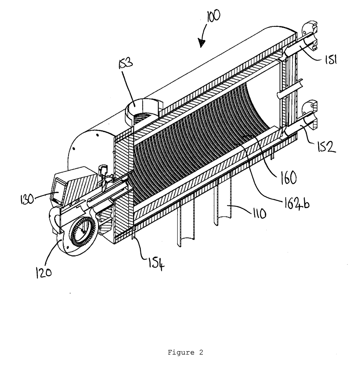
The invention describes a cassette design that can be placed close to the sides of a boiler with curved sides, allowing more cassettes to be fitted in and increasing heat transfer efficiency. The curved shape of the fluid flow passages also provides a greater surface area for heat transfer. The cassettes are made using profiling and rolling to create a strong construction.

Problems solved by technology

There may be significant limescale and debris build-up in the channels, causing negative effects on heat transfer performance of the heat exchanger.

Method used


Image

  • Condensing boiler
  • Condensing boiler
  • Condensing boiler

Examples


Embodiment Construction

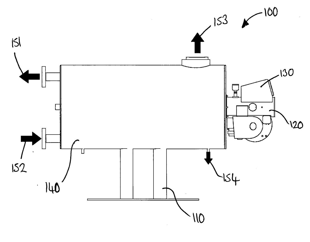
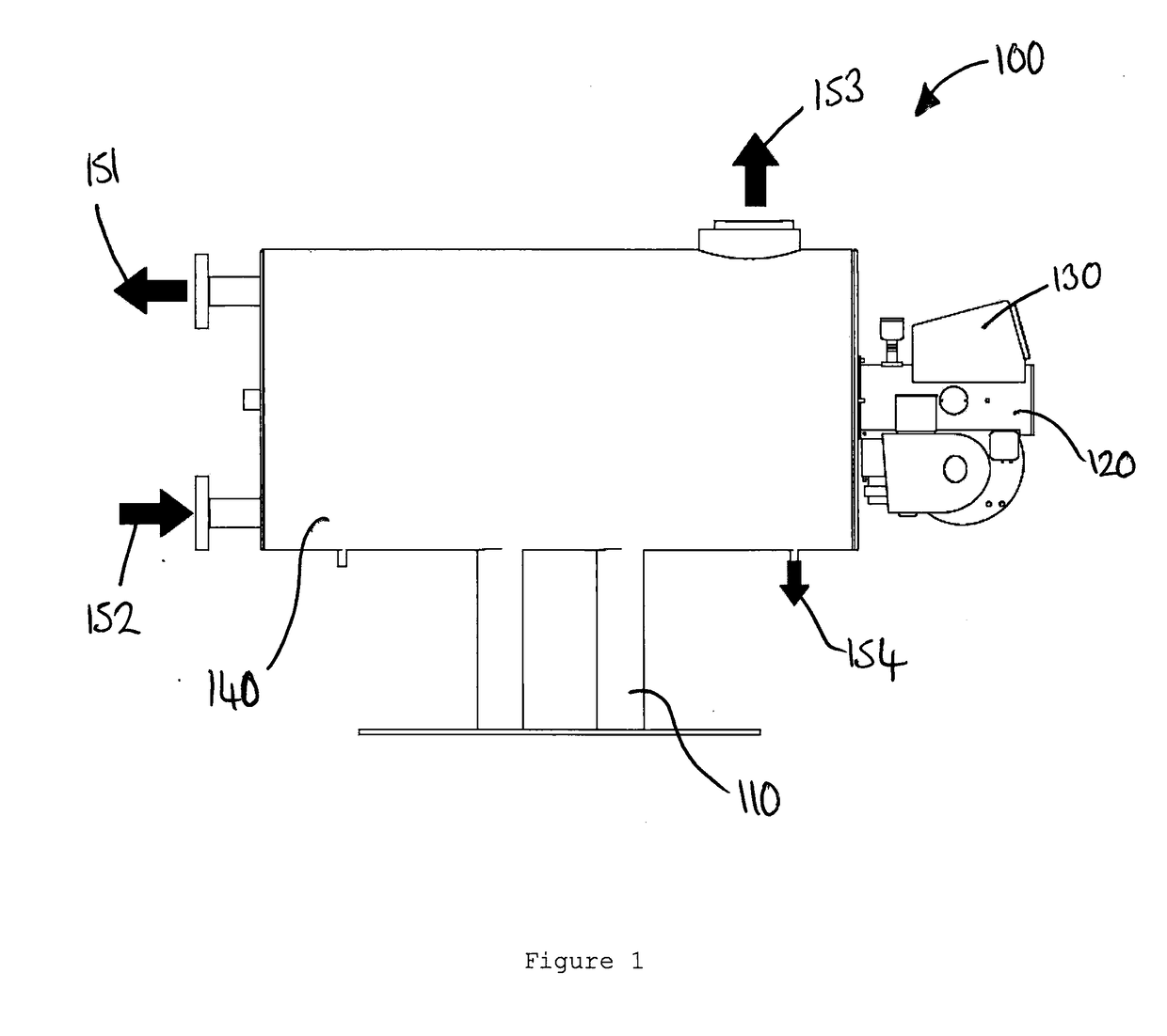
[0046]FIG. 1 shows a side view of a condensing boiler 100 according to a first embodiment of the invention.

[0047]The condensing boiler 100 comprises a cylindrical heat exchanger unit 140 on a stand 110. The stand 110 has two legs and allows the boiler to be raised off the ground. At one end (right end as shown in FIG. 1) of the cylindrical heat exchanger unit 140 is the burner 120 for the boiler 100 and a control unit 130.

[0048]The cylindrical heat exchanger unit 140 itself has four inlet / outlets 150, as follows:[0049]A water return inlet 152 for receiving water to be heated by the boiler. The water return inlet 152 is located towards the bottom of the cylindrical heat exchanger unit 140 on the opposite side to the burner 120 and control unit 130.[0050]A water flow outlet 151 for providing water that has been heated by the boiler. The outlet 151 is located above the water return inlet 152, also on the opposite side of the cylindrical heat exchanger unit 140 to the burner 120 and con...


PUM


Abstract

The invention provides a condensing boiler100 including a heat exchanger 160, the heat exchanger including at least one fluid flow cassette 162a, 162b, 163a, 163b, 164a, 164b, each cassette comprising first 181 and second 182 sheets, wherein at least the first sheet has corrugations 185, 186, 187 along a length of the sheet so as to form a number of grooves extending across a width of the sheet, wherein the second sheet is attached against the first sheet so as to enclose the grooves to form a number of fluid flow passageways 193 extending across a width of the cassette in between the first and second sheets, and wherein the cassette is substantially curved across its width such that the fluid flow passageways are substantially curved along their length. The invention also provides a method of manufacturing a heat exchanger or condensing boiler.

Description

BACKGROUND OF THE INVENTION[0001]The present disclosure relates to an improved condensing boiler.[0002]The present invention concerns condensing boilers. More particularly, but not exclusively, this invention concerns a condensing boiler including a heat exchanger. The invention also concerns a method of manufacturing a heat exchanger or condensing boiler.[0003]Heat exchangers may be made from corrugated sheets to form cassettes. Water or flue gases are able to flow in the channels formed in the corrugations so as to transfer heat with the water of flue gases outside of the channels. Such cassettes are often rectangular. There may be significant limescale and debris build-up in the channels, causing negative effects on heat transfer performance of the heat exchanger.[0004]The present invention seeks to mitigate the above-mentioned problems. Alternatively or additionally, the present invention seeks to provide an improved condensing boiler.SUMMARY OF THE INVENTION[0005]The present in...

Claims


Application Information

Patent Timeline
IPC IPC(8): F24H9/00F24H1/44F24H1/18
CPCF24H9/001F24H1/445F24H1/181F24H9/0047F24H1/406F24H1/43F24H8/00F28D7/026Y02B30/00F24H9/45F28D7/0016F28D7/1615F28D7/163F28D7/1684F28D9/0006F28D9/0012F28D9/0025F28D9/0031F28D9/0043F28D9/0093F28D2021/0024
Inventor KEMP, BRENDAN
Owner BKBD LTD
Learn More