Liquid crystal display

Inactive Publication Date: 2018-02-01
WUHAN CHINA STAR OPTOELECTRONICS TECH CO LTD
View PDF4 Cites 6 Cited by
  • Summary
  • Abstract
  • Description
  • Claims
  • Application Information

AI Technical Summary

Benefits of technology

The present invention is a new LCD design that improves alignment precision and aperture ratio. The color-resist layer, photo-spacer, and TFT layer are all formed on the same substrate, allowing for better alignment with previous layers during fabrication. The backlight module is positioned on the side closest to the first substrate, which prevents current leakage and improves display quality. Additionally, a shielding metal layer at the bottom of the second substrate prevents light reflection and increases display contrast. This design has a simple structure, saves on the fabrication of a black matrix, and provides higher alignment precision and aperture ratio.

Problems solved by technology

In the current process, it is impossible to achieve error-free alignment.

Method used


Image

  • Liquid crystal display
  • Liquid crystal display
  • Liquid crystal display

Examples


Embodiment Construction

[0026]To further explain the technical means and effect of the present invention, the following refers to embodiments and drawings for detailed description.

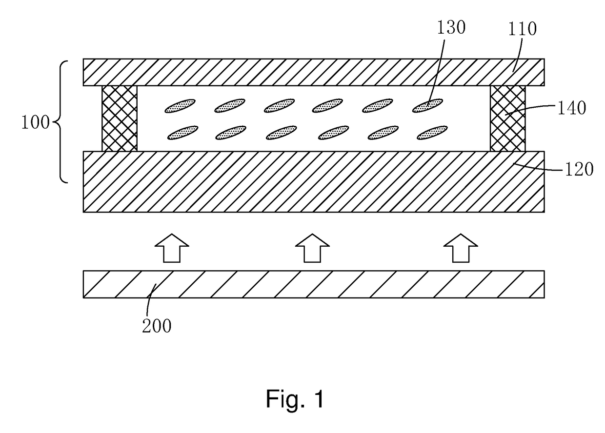
[0027]Refer to FIGS. 3-5. The present invention provides a LCD, which comprises: a liquid crystal (LC) pane 1, and a backlight module 2 disposed below the LC panel 1.

[0028]As shown in FIG. 3, the LC panel comprises a first substrate 11, a second substrate 12 disposed opposite to the first substrate 11, an LC layer 13 sandwiched between the first substrate 11 and the second substrate 12, and a sealant 14 to bond the first substrate 11 and the second substrate 12.

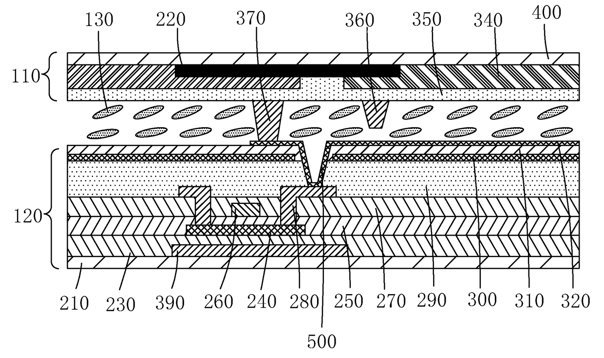
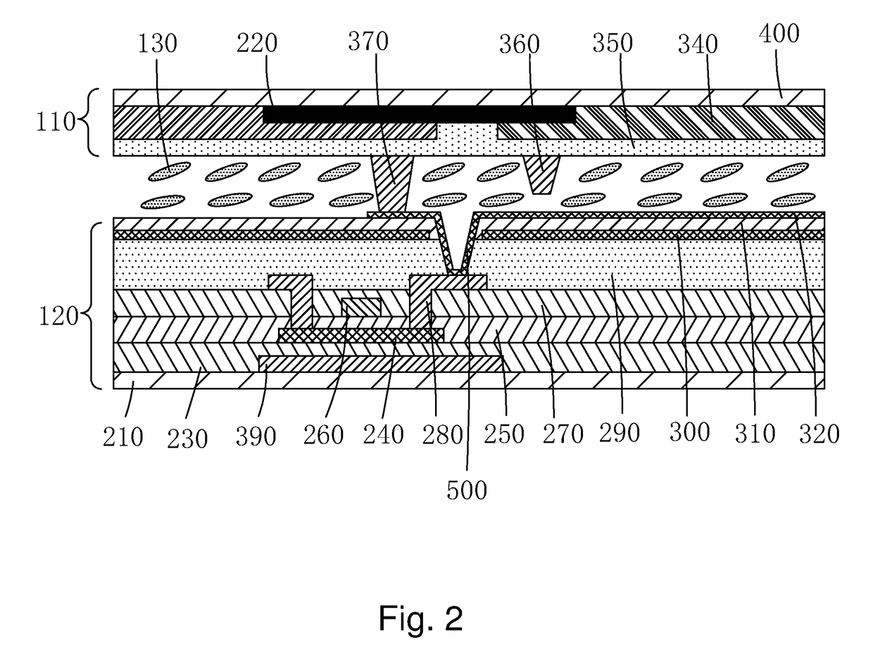
[0029]As shown in FIG. 4, the second substrate 12 comprises a base substrate 21, a shielding metal layer 22 disposed on the base substrate 21, a first insulating layer 23 disposed on the base substrate 21 and the shielding metal layer 22, a TFT layer 20 disposed on the first insulating layer 23, a first passivation layer 33 disposed on the TFT layer 20, a color-resist laye...


PUM


Abstract

The invention provides an LCD, wherein the color-resist layer, photo-spacer and TFT layer are disposed at the same second substrate of LC panel to achieve higher alignment precision by reducing offset between layers of second substrate; also, because the backlight module is disposed at the side near first substrate of LC panel and second substrate uses a top gate structure, when the backlight module light enters from first substrate side of LC panel, the gate shields the channel region of polysilicon layer to improve current leakage of second substrate; moreover, the shielding metal layer at the bottom of the second substrate side is made of a black metal, the shielding metal layer at the bottom can prevent reflection of light from second substrate side caused by metal to reduce contrast. As such, the present invention has a simple structure, and saves black matrix fabrication compared to conventional technology.

Description

BACKGROUND OF THE INVENTION1. Field of the Invention[0001]The present invention relates to the field of display, and in particular to a liquid crystal display (LCD).2. The Related Arts[0002]The liquid crystal display (LCD) provides the advantages of thin, low power consumption, radiation-free, and so on, and is widely applied to, such as, mobile phones, personal digital assistant (PDA), digital camera, computer monitors and notebook computers.[0003]The conventional liquid crystal display devices on the market are mostly of the backlight type, comprising a case, a liquid crystal panel and a backlight module disposed inside the case. The traditional structure of the liquid crystal panel comprises a color filter (CF) substrate, a TFT array substrate, and a liquid crystal layer sandwiched between two substrates. The working principle is to apply a driving voltage to the two glass substrates to control the rotation of the liquid crystal molecules of the liquid crystal layer to refract th...

Claims


Application Information

Patent Timeline
IPC IPC(8): G02F1/1335G03F7/00G09G3/36G02F1/1368
CPCG02F1/1335G02F1/1368G02F1/133514G03F7/0007G09G3/36G02F1/133621G02F1/1343G02F2001/136218G02F1/133512G02F1/133615G02F1/13685G02F1/13394G02F1/1362G02F1/133567G02F1/136218G02F1/136222G02F1/136209
Inventor LI, YAFENG
Owner WUHAN CHINA STAR OPTOELECTRONICS TECH CO LTD
Why Eureka
Try Eureka