
Developing apparatus, electrophotographic process cartridge, and electrophotographic image forming apparatus

a development apparatus and process technology, applied in the direction of electrographic process apparatus, optics, instruments, etc., can solve the problems of inability to obtain a uniform image, and insufficient charge amount of the toner layer to be formed on the developing roller, etc., to achieve excellent triboelectric charge imparting ability, improve toner-conveying force, and high density

Active Publication Date: 2018-02-01
CANON KK
View PDF0 Cites 5 Cited by
  • Summary
  • Abstract
  • Description
  • Claims
  • Application Information

AI Technical Summary

Benefits of technology

This patent is about a developing apparatus and process cartridge that can improve toner-conveying force and triboelectric charge imparting ability for toner, especially when printing high-density images. This invention helps ensure stable and high-quality electrophotographic images can be produced in various environments.

Problems solved by technology

However, when the reduction in torque at the time of the rotation is performed by reductions in diameters of the developing roller and the developer-supplying roller, or the reduction in indentation amount of any such member or the reduction in peripheral speed difference between the members, there is a problem in that the charge amount of the toner layer to be formed on the developing roller becomes insufficient and hence it is difficult to obtain a uniform image.
Further, there is a problem in that the charge amount of the toner layer to be formed on the developing roller is liable to be insufficient during printing of an image having a high density such as solid black (region having a maximum image density in a large area).
When such a developer regulating member is used in the formation of an electrophotographic image, “fogging immediately after printing of solid black” is liable to occur in the electrophotographic image to be obtained.

Method used


Image

  • Developing apparatus, electrophotographic process cartridge, and electrophotographic image forming apparatus
  • Developing apparatus, electrophotographic process cartridge, and electrophotographic image forming apparatus
  • Developing apparatus, electrophotographic process cartridge, and electrophotographic image forming apparatus

Examples


example 1

[0154][1. Production and Physical Property Evaluation of Developing Apparatus 1]

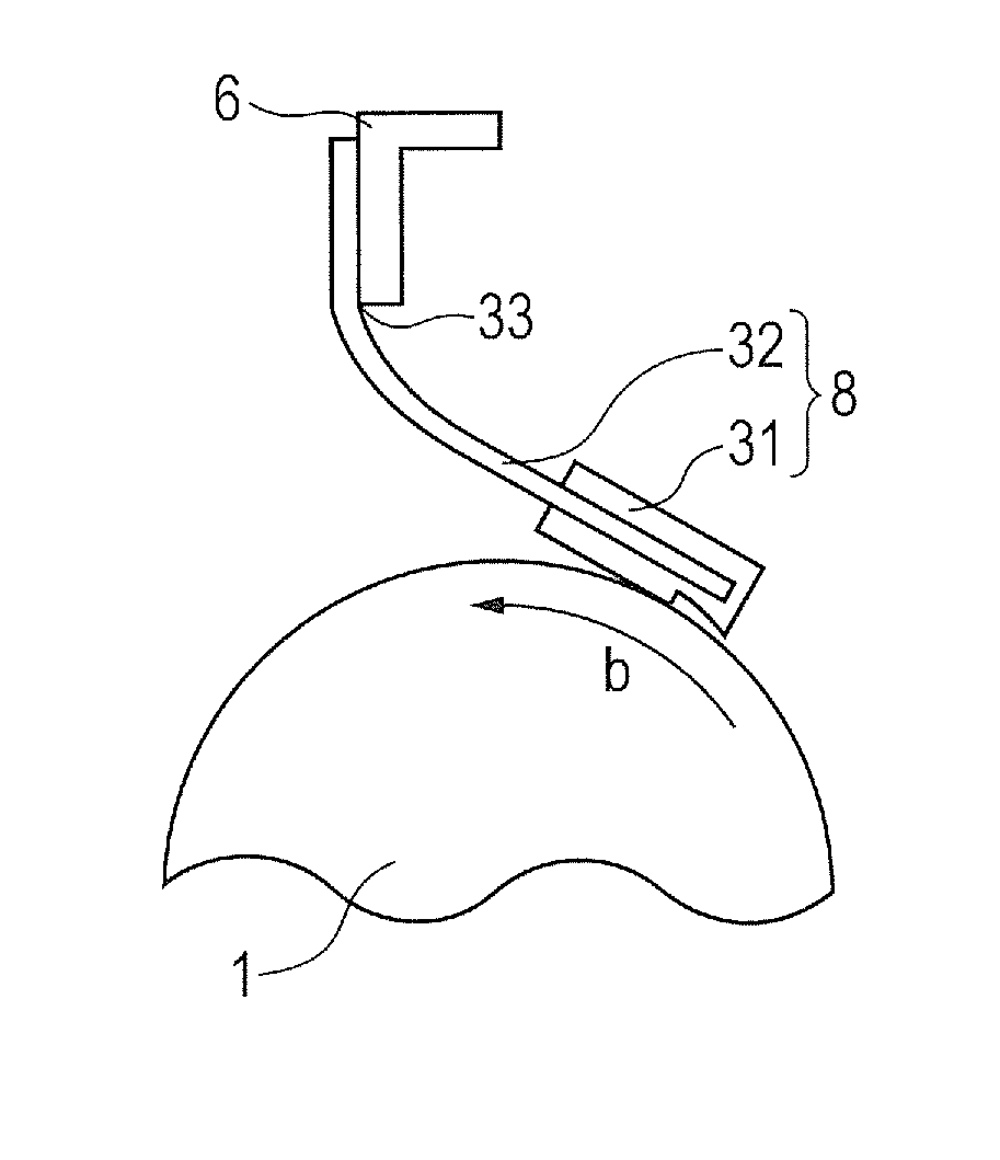
[0155]FIG. 10 is an illustration of an example of a sectional view for illustrating a part of a process cartridge including a developing apparatus produced in relation to Example 1 to Example 108, which is taken along a direction perpendicular to the longitudinal direction of the process cartridge. First, a gear of the process cartridge (Product name: CE263A Magenta, manufactured by Hewlett-Packard Company) was reconstructed for the purpose of a reduction in torque so that a developer-supplying roller is rotated in a forward direction c with respect to a rotating direction b of the developing roller at equal speed. Next, the developer regulating member was removed from the process cartridge, and the developer regulating member 1 obtained in Production Example B1 was mounted. Further, the developing roller was removed from the process cartridge, and the developing roller 1 obtained in Production Example A...


PUM


Abstract

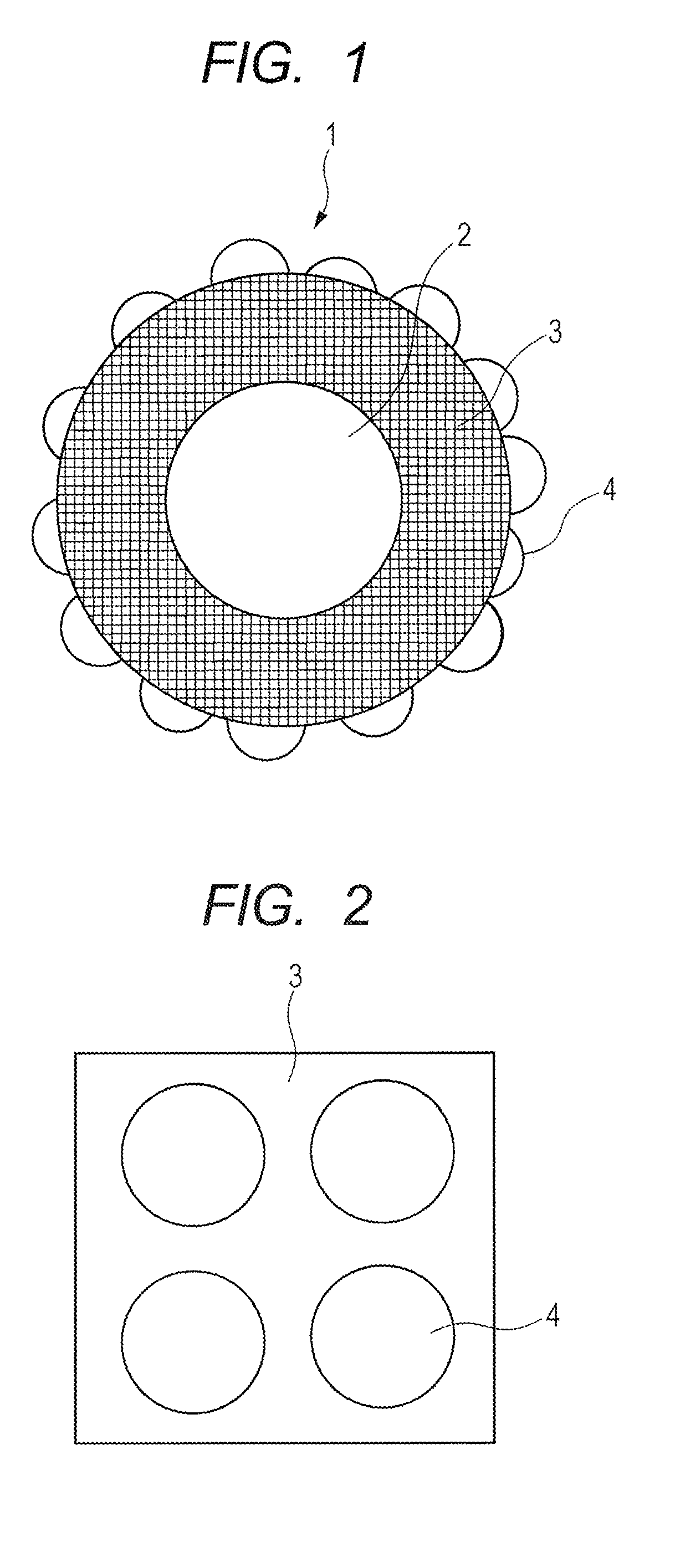
The developing apparatus includes: a developing roller rotatable in a first rotation direction; and a developer regulating member, wherein the developing roller includes: a substrate; an electro-conductive elastic layer on the substrate; and insulating domains on the electro-conductive elastic layer, wherein the electro-conductive elastic layer has a certain Martens hardness, the developing roller has a surface including surfaces of the insulating domains and a surface of the electro-conductive elastic layer, which is uncovered with the insulating domains at a certain area ratio, wherein the developer regulating member comprises: an abutting portion which is in contact with the surface of the developing roller, and a certain projection portion extending to an upstream side from the abutting portion in the first rotation direction, the developing apparatus has a certain gap between a side of the projection portion facing to the developing roller, and the surface of the developing roller.

Description

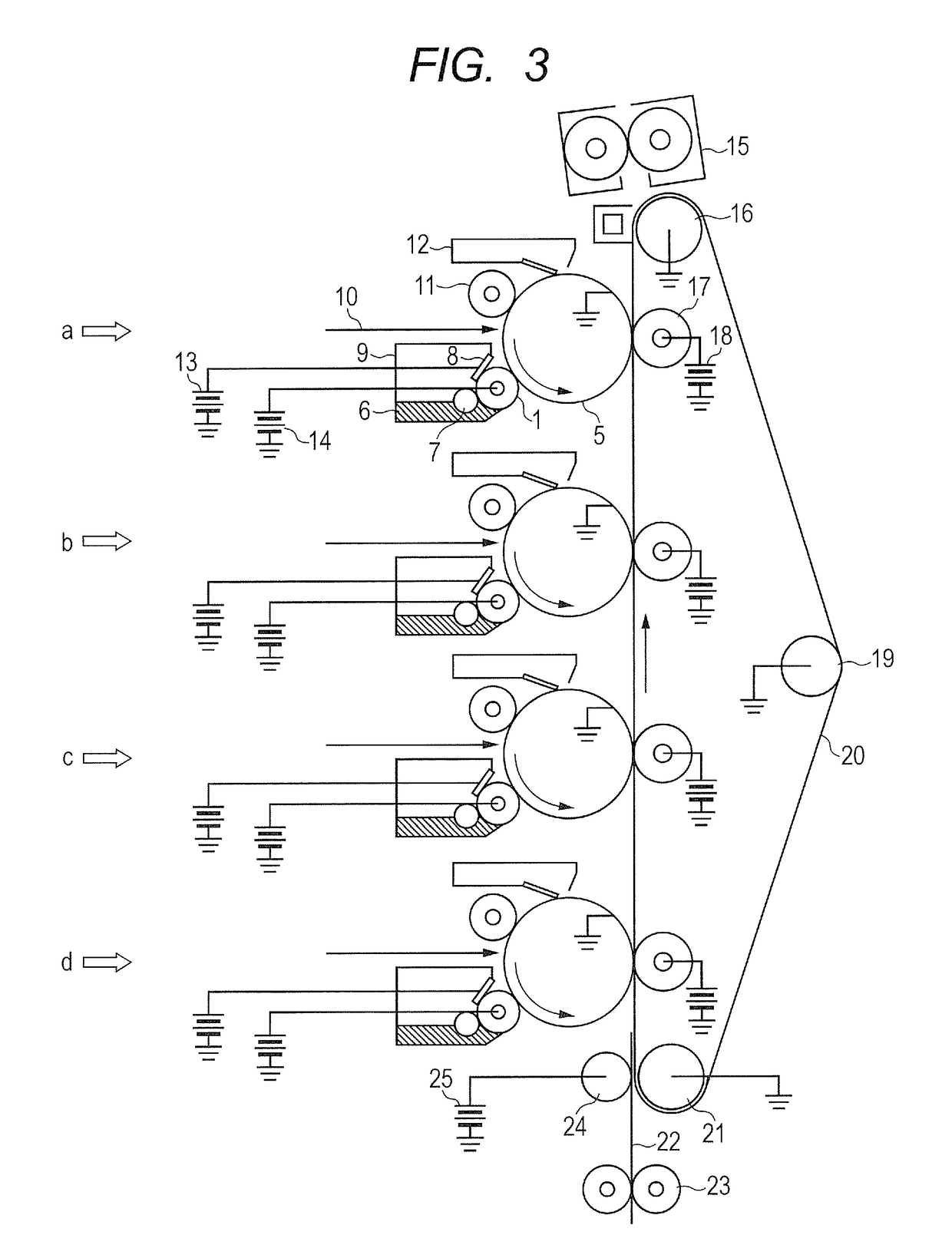
BACKGROUND OF THE INVENTIONField of the Invention[0001]The present invention relates to a developing apparatus, an electrophotographic process cartridge, and an electrophotographic image forming apparatus.Description of the Related Art[0002]A developing method involving using a nonmagnetic one-component toner has been known as the image forming method of an electrophotographic image forming apparatus, such as a copying machine or an optical printer. Specifically, a photosensitive member serving as a rotatable electrostatic latent image-bearing member is charged by a charging unit, such as a charging roller, and an electrostatic latent image is formed by exposing the surface of the charged photosensitive member to laser light. Next, in the developing apparatus of the image forming apparatus, a toner in a developer container is applied onto a developing roller by a developer-regulating member, and the electrostatic latent image is developed with the toner at a contact portion between ...

Claims


Application Information

Patent Timeline
Patent Type & Authority Applications(United States)
IPC IPC(8): G03G15/08
CPCG03G15/0812G03G15/0808G03G15/0818
Inventor SUGIYAMA, RYOSAKURAI, YUJIOGAWA, YOSHINOBUISHIDA, KAZUTOSHIOKUDA, MITSURU
Owner CANON KK
Learn More