Headrest having speaker

a headrest and speaker technology, applied in the field of headrests, can solve the problems of difficult to feel stereo effect, difficult to exhibit stereo feeling, separable distance, etc., and achieve the effect of preventing degraded acoustic characteristics, preventing interference with sound output by adjacent other speakers, and preventing higher sound pressure level

Active Publication Date: 2018-02-01
DELTA TOOLING CO LTD
View PDF3 Cites 20 Cited by
  • Summary
  • Abstract
  • Description
  • Claims
  • Application Information

AI Technical Summary

Benefits of technology

[0017]According to the present invention, the front surfaces of each of the speakers are installed with the sound-emitting direction regulating members formed of the annular portions that project forward by a predetermined distance, and the three-dimensional fabric is tensioned and arranged so as to cover the front surface side of the sound-emitting direction regulating members. Since the three-dimensional fabric has a predetermined thickness, when the three-dimensional fabric is pressed against the annular portions that compose the sound-emitting direction regulating members, the annular portions bite into the three-dimensional fabric. The annular portions are provided so as to surround the diaphragms of the speakers. Sound output from the speakers passes insides of the annular portions. However, since a periphery of a region of the three-dimensional fabric where the sound passes is supported by the bite of the annular portions, the flapping widely in response to sound around the resonance frequency is prevented, and the acoustic characteristics can be prevented from being degraded. In addition, for the output sound of the spe

Problems solved by technology

In addition, even when a plurality of speakers are used, a stereo effect is hard to be felt when the speakers are too close.
H

Method used


Image

  • Headrest having speaker
  • Headrest having speaker
  • Headrest having speaker

Examples


Embodiment Construction

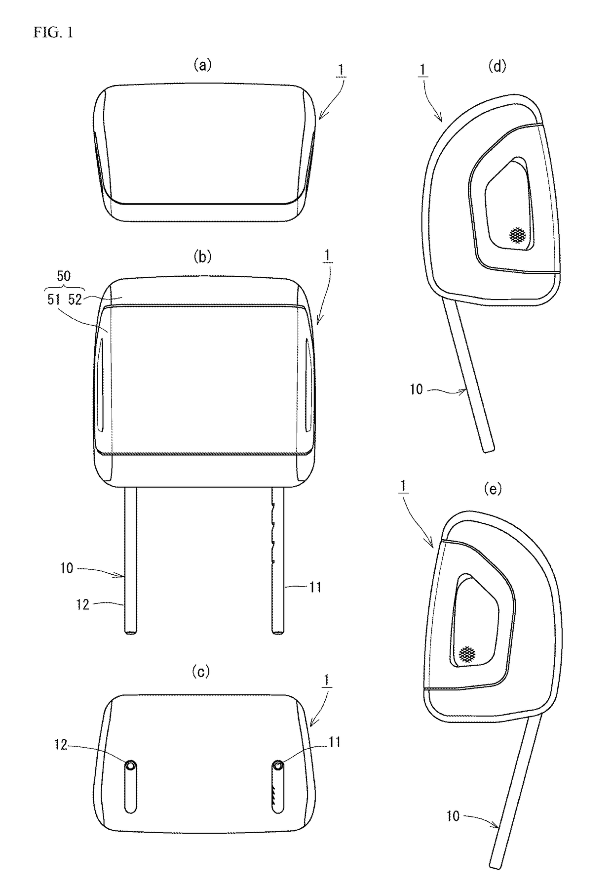
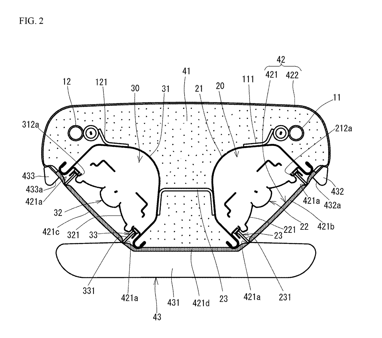
[0033]Following further describes the present invention in detail on the basis of the embodiments shown in the drawings. FIG. 1 to FIG. 5 are diagrams showing a first embodiment of the present invention. A headrest having a speaker (hereinafter, simply referred to as “headrest”) 1 of the present embodiment is configured to have a headrest frame 10, speakers 20, 30, a cushioning layer 40, a skin member 50, and the like.

[0034]In the present embodiment, the headrest frame 10 is formed in a substantially U-shape, extends in a substantially perpendicular direction, and is configured to have a right and left pair of longitudinal frame parts 11, 12 that are connected to each other in upper parts. The longitudinal frame parts 11, 12 are inserted to a pair of guide parts (not shown) respectively that are supported by a back frame of a seat back part with predetermined intervals in right and left. The position of the longitudinal frame parts 11, 12 can be adjusted to be an appropriate height....


PUM


Abstract

The present invention prevents a three-dimensional fabric arranged in front surfaces of speakers from flapping due to sound. In the respective front surface sides of, sound-emitting direction regulating members that include annular portions that project forward by a predetermined distance are arranged. A three-dimensional fabric is tensioned and arranged so as to cover the front surface sides of the sound-emitting direction regulating members. When the three-dimensional fabric is pressed against the annular portions configuring the sound-emitting direction regulating members, the annular portions bite into the three-dimensional fabric since the three-dimensional fabric has a predetermined thickness. The annular portions are provided so as to surround diaphragms of the speakers. Sound output from the speakers passes inside the annular portions. However, the periphery of a region of the three-dimensional fabric in which sound passes is supported by the biting of the annular portions, thereby preventing the three-dimensional fabric from flapping widely in response to the sound.

Description

TECHNICAL FIELD[0001]The present invention relates to a headrest having a speaker.BACKGROUND ART[0002]Patent Document 1 discloses a headrest as follows. That is, the headrest includes: a substantially rectangular member that forms a frame of the headrest; a pad member that is arranged in a front surface side of the substantially rectangular member; first net members that are arranged in right and left of a front surface side of the pad member; a slab member that is arranged between the right and left first net members; and a skin member that covers the right and left first net members and the slab member.[0003]The substantially rectangular member that forms the frame of the headrest includes a panel member arranged in a front surface side, and a box-shaped cover member in which the panel member is mounted to a front surface opening. In an interior space covered by the panel member and the cover member, right and left pair of speakers is installed. In the panel member, the pad member...

Claims


Application Information

Patent Timeline
IPC IPC(8): H04R1/02A47C7/72B60N2/48A47C7/38
CPCH04R1/028H04R2499/13H04R1/023A47C7/38A47C7/72B60N2/4876B60R11/02H04R1/02H04R1/32B60N2/80B60N2/879B60N2/818A47C7/727
Inventor FUJITA, ETSUNORIOGURA, YUMIUCHIYAMA, TAKAOTAKENAKA, KAZUHIROYASUI, KAZUNARI
Owner DELTA TOOLING CO LTD
Why Eureka
Try Eureka