Air ionization systems and components

a technology of air ionization and components, applied in the field of air cleaning, can solve the problems of insufficient ionization level to fully clean and/or sanitize a particular air stream, prior approaches to air filtration and/or ionization suffer from various drawbacks, and achieve the effect of reducing cross-sectional area and greater ionization

Active Publication Date: 2018-02-08
IONAER INT ARIZONA LLC
View PDF8 Cites 8 Cited by
  • Summary
  • Abstract
  • Description
  • Claims
  • Application Information

AI Technical Summary

Benefits of technology

[0005]An air ionization unit is preferably an integral, one-piece unit, so it can be removed from a surface to which it is mounted. That way it can be replaced as a single unit without having to disassemble it. In one preferred embodiment, the air ionization unit has a support plate that mounts directly or indirectly to the outside surface of an air passageway or other space (collectively, “duct”) that includes air to be cleaned. The support plate is connected to a surface defining a duct by fasteners that pass through the support plate and through the material of the surface duct. The air ionization tube and ozone dampening catalyst preferably are attached to and extend outward from the support plate and into the air duct. The fasteners holding the support plate on the exterior surface of the air duct can be removed to remove the support plate, air ionization tube and / or replace the entire air ionization unit.
[0007]Also disclosed are alternative ionization tubes and tube configurations that can be used to reduce the cross-sectional area in which the tube(s) are positioned and / or that provide greater ionization in the same cross-sectional area as known ionization tubes.

Problems solved by technology

Prior approaches to air filtration and / or ionization suffer from various drawbacks.
For example, certain air ionization systems, in order to avoid releasing an unacceptable level of ozone, generate ionization levels that are insufficient to fully clean and / or sanitize a particular air stream.
Moreover, some air ionization systems have suffered from a lack of configurability and / or intelligent control.
Yet other air ionization systems have been complex, expensive, and / or lacking in modular configuration and / or serviceability.

Method used


Image

  • Air ionization systems and components
  • Air ionization systems and components
  • Air ionization systems and components

Examples


Embodiment Construction

[0050]The following description is of various exemplary embodiments only, and is not intended to limit the scope of the present disclosure in any way. As will become apparent, various changes may be made in the function and arrangement of the elements described in these embodiments without departing from the scope of the appended claims.

[0051]It should be noted that many alternative or additional functional relationships or physical connections may be present in a practical ionization system or related methods.

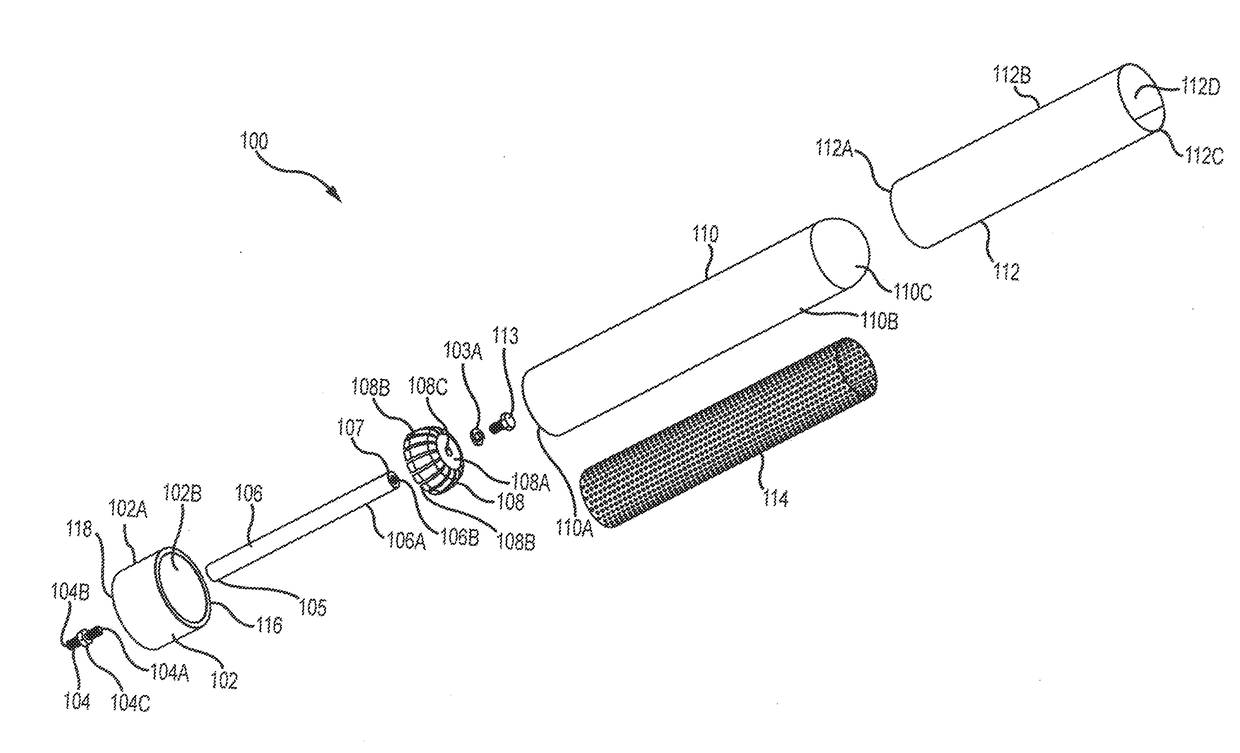
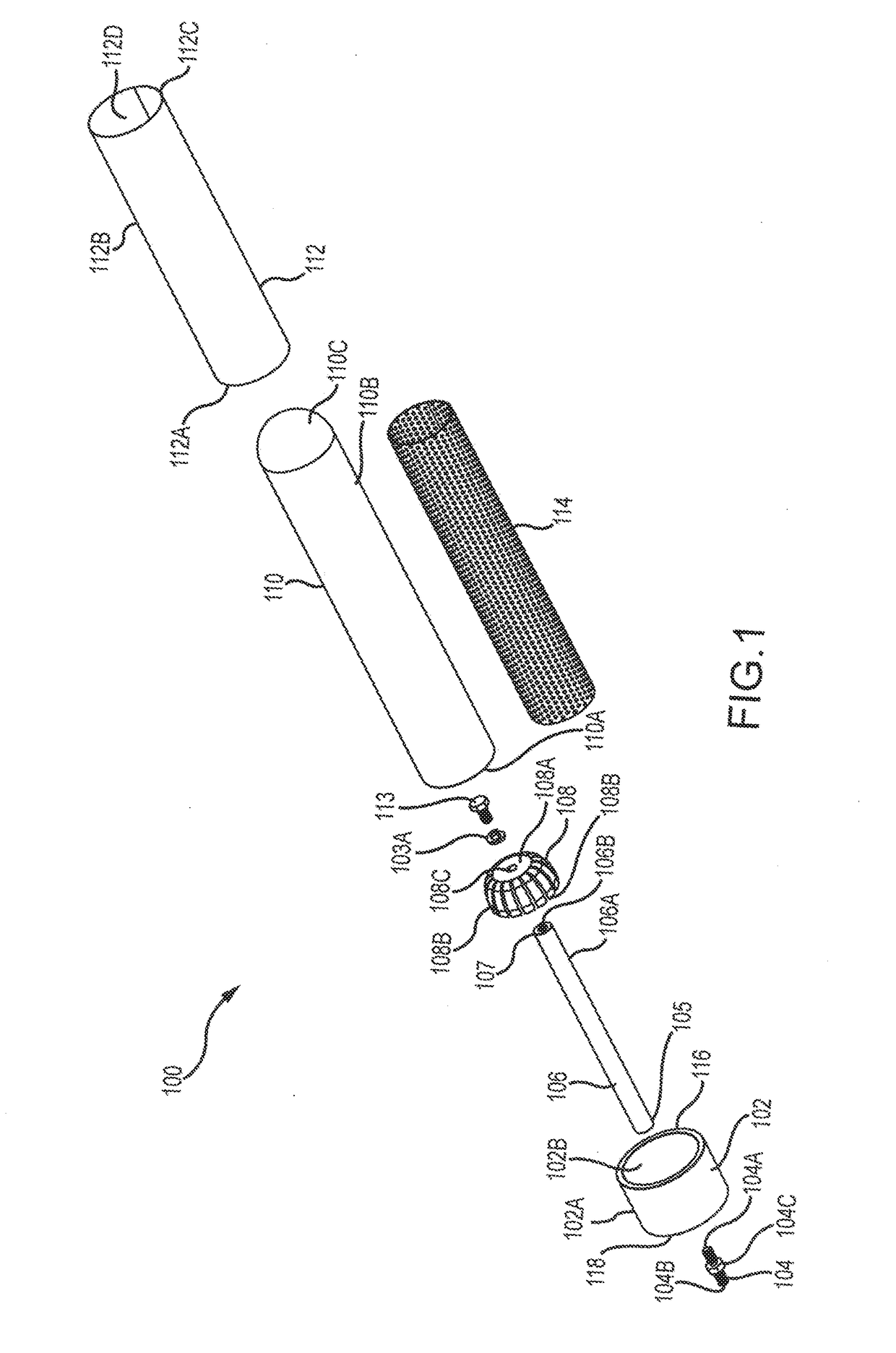
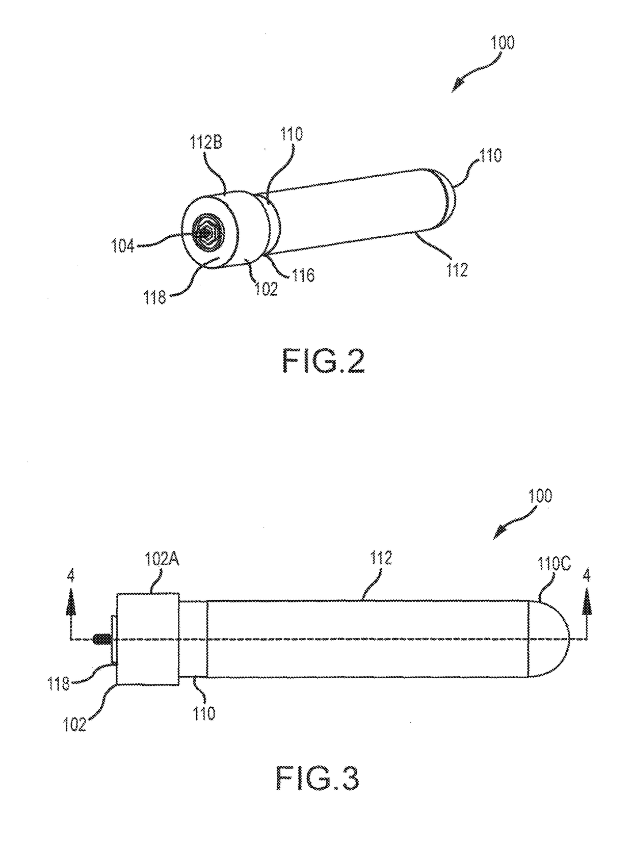
[0052]Turning now to FIGS. 1 through 6, a module 100 for ionizing air is shown. Module 100 as shown preferably has an end cap or “base”102, an adapter 104, a coupler 106, an ion dispenser 108, a tube 110, an outer electrode 112, and an inner electrode 114. Base 102 is preferably comprised of any suitable plastic, for example injection-molded ABS (but preferably not ABS-PC), although any suitable material may be used. The purpose of base 102 is to receive coupler 106, ion dispe...


PUM

PropertyMeasurementUnit
thicknessaaaaaaaaaa
thicknessaaaaaaaaaa
frequenciesaaaaaaaaaa

Abstract

Ionization systems configured with a catalyst-bearing sleeve provide improved filtration while filtering ozone. Modular configurations provide for serviceability and replaceability. System controls may be used to monitor particulates, temperature, humidity, and other relevant factors and adjust an ionization level accordingly.

Description

CROSS REFERENCE TO RELATED APPLICATIONS[0001]This Application claims priority to U.S. patent application Ser. Nos. 15 / 156,755, 15 / 156,735, and 15 / 156,771, all to Bender et al. and filed on May 17, 2016. The disclosures of these Applications are incorporated herein by reference.TECHNICAL FIELD[0002]The present disclosure relates to air cleaning, and in particular to the removal of particulates in air by utilizing ionization.BACKGROUND[0003]Prior approaches to air filtration and / or ionization suffer from various drawbacks. For example, certain air ionization systems, in order to avoid releasing an unacceptable level of ozone, generate ionization levels that are insufficient to fully clean and / or sanitize a particular air stream. Moreover, some air ionization systems have suffered from a lack of configurability and / or intelligent control. Yet other air ionization systems have been complex, expensive, and / or lacking in modular configuration and / or serviceability. These and other drawbac...

Claims


Application Information

Patent Timeline
Patent Type & Authority Applications(United States)
IPC IPC(8): B01D53/32B01D53/86
CPCB01D2259/818B01D53/32B01D53/8675B01D53/30B01D2257/106B01D2258/06B01D2259/4508B01D2259/80F24F8/30A61L9/00A61L9/22A61L2209/11A61L2209/13A61L2209/14B01D46/0027B01D46/0028B01D46/0038B01D53/323B01D53/88B01D2255/2073B01D2255/20761B01D2257/90H01T23/00F24F8/192F24F8/98
Inventor BENDER, TIMOTHY MARKPAULEY, PERRYROPER, BRIAN KEITHROPER, TODD KENNETH
Owner IONAER INT ARIZONA LLC
Why Eureka
Try Eureka