

Bending mold device for bidirectional pipe bending
- Summary
- Abstract
- Description
- Claims
- Application Information
AI Technical Summary
Benefits of technology
Problems solved by technology
Method used
Image

Examples
Embodiment Construction
[0024]The specific implementing solutions of the present invention are described in detail in combination with the drawings.
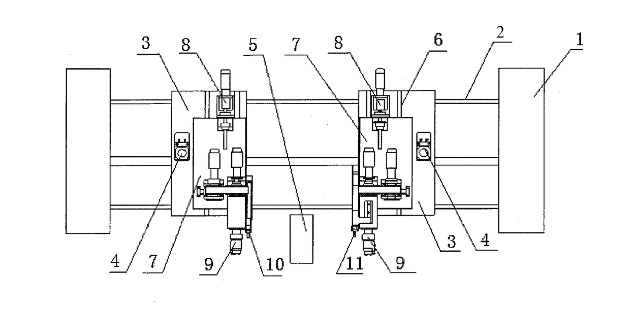
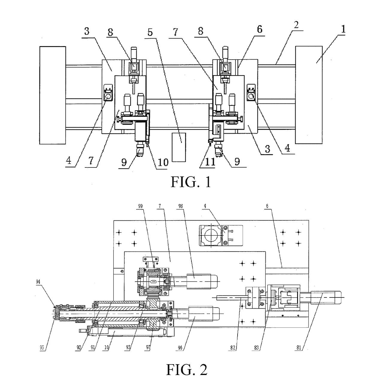
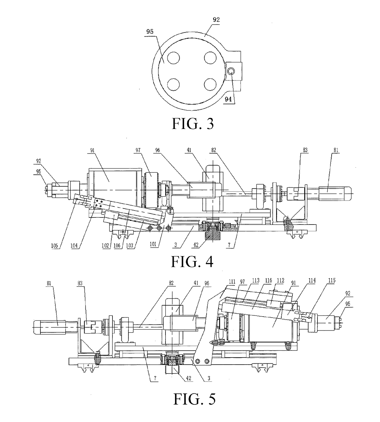
[0025]As shown in FIGS. 1-5, a bending and molding mechanism comprises a base 1, wherein the base 1 is provide with a transverse sliding rail 2, two transverse sliding bases 3 are disposed on the transverse sliding rail 2 in a sliding manner, and the base 1 is provided with a transverse driving device 4 driving the transverse sliding bases 3. The transverse driving device 4 comprises a rack (not shown in the drawing) disposed on the base 1, the transverse sliding base 3 is provided with a transverse driving motor 41, and an output shaft of the transverse driving motor 41 downwards penetrates out of the transverse sliding base 3 and is connected to a gear 42 matched with the rack. The base 1 is provided with a central clamping device 5 which can clamp the wire and can rotate around a central axis of the wire between the two transverse sliding bases 3.
[0026]The t...
PUM
| Property | Measurement | Unit |
|---|---|---|
| Angle | aaaaa | aaaaa |
| Radius | aaaaa | aaaaa |
Abstract
Description
Claims
Application Information