This helps you quickly interpret patents by identifying the three key elements:
Problems solved by technology
Method used
Benefits of technology
Benefits of technology
The patent is about a control system for vehicles that improves how electric power is used throughout the vehicle. This system can help to make the vehicle more efficient in using electricity, which can help to improve its overall performance.
Problems solved by technology
When electric power exceeding the chargeable power is not used for charging but is wasted as heat, the electric power exceeding the chargeable power is useless.
In this case, when an operating state of the electrical loads varies and electric power consumed by the electrical loads becomes greater than the excess power, the electric power required for operation of the electrical loads cannot be covered with only the excess power and thus electric power is supplied from a secondary battery such as a battery to the electrical loads.
However, when electric power consumed by the electrical loads increases excessively, an amount of electric power supplied from the secondary battery to the electrical loads increases and thus there is concern that electric power use efficiency of a vehicle as a whole will decrease.
Accordingly, since the electric power consumed by the electrical load is limited to the excess power as an upper limit, it is possible to limit the electric power supplied from the secondary battery to the electrical load due to operation of the electrical load.
As a result, it is possible to reduce electric power which is not used to charge the secondary battery in the future and is wasted.
For example, when there is at least the occurrence history, the charging of the secondary battery has been limited already by a decrease in the chargeable power of the secondary battery.
Method used
Image
Click on the blue label to locate the original text in one second.
Reading with bidirectional positioning of images and text.
Examples
first embodiment
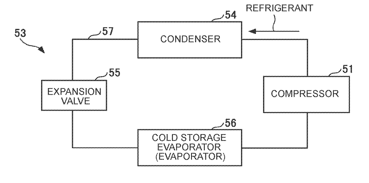
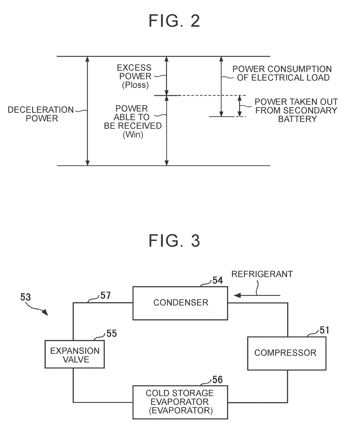
[0085]FIG. 6 is a flowchart illustrating an example of a process flow of air-conditioning control by the air-conditioning ECU 52.
[0086]The air-conditioning ECU 52 repeatedly performs processes from the start to the end illustrated in FIG. 6 at predetermined intervals.
[0087]In Step S3, the air-conditioning ECU 52 determines whether the air-conditioning device 53 in operation is in a warm-up state or a cool-down state. When it is determined that the air-conditioning device 53 in operation is in a warm-up state or a cool-down state, the air-conditioning ECU 52 does not allow the air-conditioning device 53 in operation to perform air-conditioning control in consideration of the power able to be received Win (Step S7). When it is determined that the air-conditioning device 53 in operation is not in a warm-up state or a cool-down state, the air-conditioning ECU 52 allows the air-conditioning device 53 in operation to perform air-conditioning control in consideration of the power able to b...
second embodiment
[0100]FIG. 8 is a flowchart illustrating an example of a process flow of air-conditioning control by the air-conditioning ECU 52. The air-conditioning ECU 52 repeatedly performs processes from the start to the end illustrated in FIG. 6 at predetermined intervals.
[0101]In Step S11, the air-conditioning ECU 52 acquires a target blowout temperature TAO and a measured indoor temperature Tr. The target blowout temperature TAO indicates a target value of the temperature of air which is blown to the vehicle interior by the air-conditioning device 53 and is set depending on a request from a user. The request from the user is input from an on-board interface unit (for example, a switch, a touch panel, or a microphone) that receives the request from the user. The measured indoor temperature Tr indicates a measured temperature of the vehicle interior.
[0102]In Step S13, the air-conditioning ECU 52 calculates an air temperature difference ΔTA between the target blowout temperature TAO and the me...
third embodiment
[0123]FIG. 11 is a flowchart illustrating an example of a process flow of the air-conditioning control in consideration of the power able to be received Win according to a third embodiment. FIG. 11 illustrates a process flow of performing process details of Step S27 in FIG. 8.
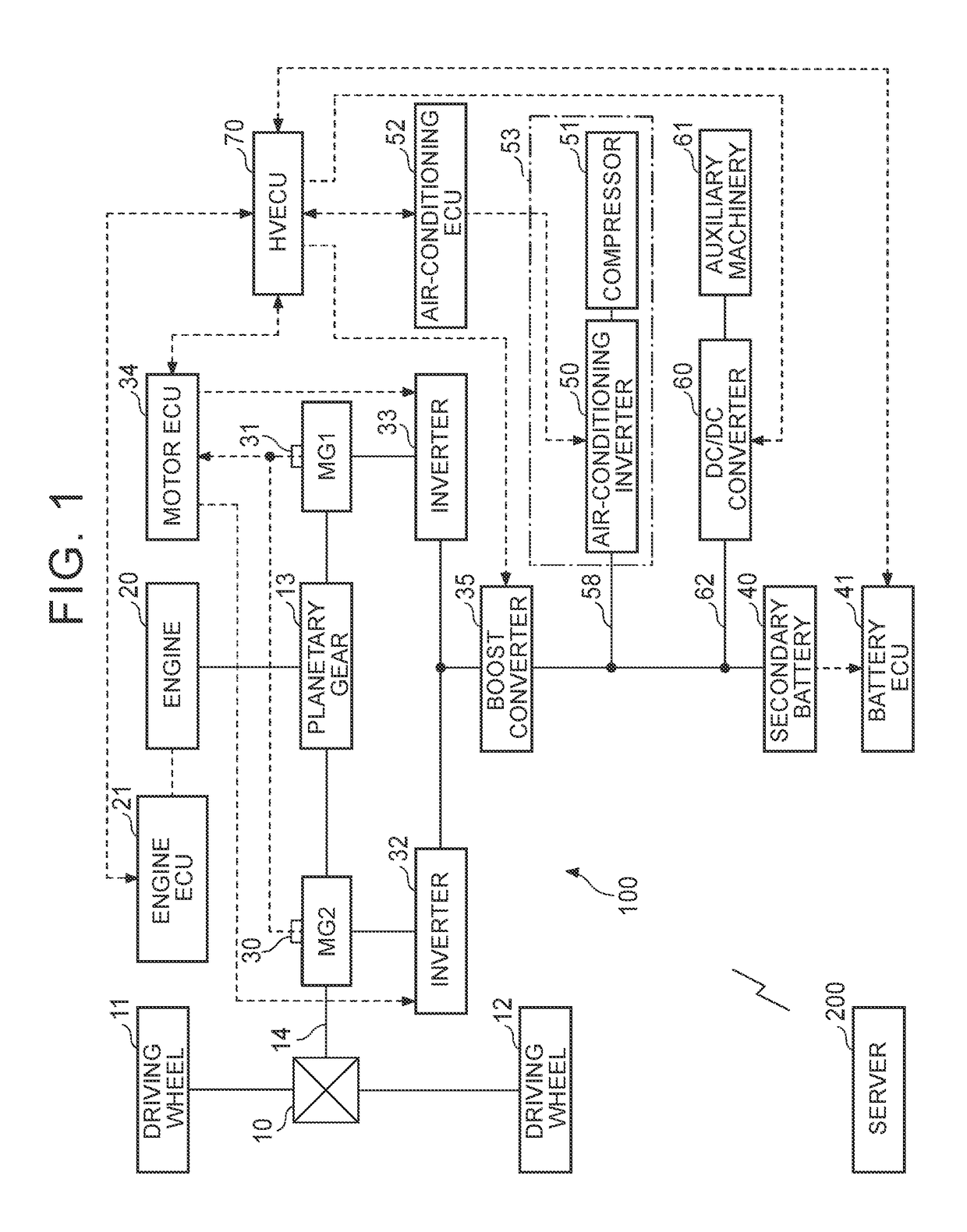
[0124]In Step S220, the HV ECU 70 calculates required deceleration power Pr which needs to be generated in the drive shaft 14 in decelerating the vehicle and acquires a power able to be received Win from the battery ECU 41.
[0125]In Step S221, the HV ECU 70 calculates excess power Ploss by subtracting the power able to be received Win from the required deceleration power Pr.
[0126]In Step S222, the HV ECU 70 determines whether the excess power Ploss is equal to or greater than a predetermined threshold value B. The threshold value B is set to, for example, zero.
[0127]The HV ECU 70 performs the process of Step S223 when the excess power Ploss is equal to or greater than the threshold value B, and performs the proc...
PUM
Abstract
A control system for a vehicle includes: a motor-generator to regenerate an electric power; a secondary battery to be charged with the electric power regenerated by the motor-generator; an electrical load to be activated with an electric power supplied from at least one of the motor-generator and the secondary battery; a power supply device to supply the electrical load with the electric power generated by the motor-generator based on a deceleration power generated by a braking operation of the vehicle; and an electronic control unit to calculate excess power which is electric power exceeding chargeable power with which the secondary battery is chargeable of a required deceleration power required by the braking operation, and to control the power supply device in accordance with a command value for causing the electric power supplied from the power supply device to the electrical load to be less than the excess power.
Description
CROSS-REFERENCE TO RELATED APPLICATIONS[0001]This application claims priority to Japanese Patent Application No. 2016-152360 filed on Aug. 2, 2016, incorporated herein by reference in its entirety.BACKGROUND1. Technical Field[0002]The disclosure relates to a control system for a vehicle.2. Description of Related Art[0003]In a vehicle that can generate regenerative power, even when regenerative power is generated, a battery cannot be charged with electric power exceeding electric power with which the battery can be charged (chargeable power). When electric power exceeding the chargeable power is not used for charging but is wasted as heat, the electric power exceeding the chargeable power is useless. In order to prevent such uselessness of electric power, a technique of supplying regenerative energy to an engine heater when chargeable power of a battery is low at the time of regeneration using a motor is known (for example, Japanese Patent Application Publication No. 2015-174601 (JP ...
Claims
Application Information
Patent Timeline
Application Date:The date an application was filed.
Publication Date:The date a patent or application was officially published.
First Publication Date:The earliest publication date of a patent with the same application number.
Issue Date:Publication date of the patent grant document.
PCT Entry Date:The Entry date of PCT National Phase.
Estimated Expiry Date:The statutory expiry date of a patent right according to the Patent Law, and it is the longest term of protection that the patent right can achieve without the termination of the patent right due to other reasons(Term extension factor has been taken into account ).
Invalid Date:Actual expiry date is based on effective date or publication date of legal transaction data of invalid patent.

