Image forming apparatus

a technology of image forming apparatus and miniaturization, which is applied in the direction of electrographic process apparatus, instruments, optics, etc., can solve the problems of reducing image quality and difficulty in maintaining the miniaturization of the apparatus, and achieve the effect of maintaining the miniaturization

Active Publication Date: 2018-02-08
CANON KK
View PDF1 Cites 9 Cited by
  • Summary
  • Abstract
  • Description
  • Claims
  • Application Information

AI Technical Summary

Benefits of technology

[0013]According to an embodiment of the present invention, it is possible to make the surface of an intermediate transfer member have an optimum potential for primary transfer while maintaining miniaturization.

Problems solved by technology

Therefore, when the surface potential of the photosensitive drum is largely changed to be adjusted, a reduction in image quality is caused.
That is, in order to slightly adjust various fluctuations caused by a surrounding environment or the use situation of the body of the image forming apparatus, it is necessary to further increase the number of Zener diodes serving as voltage maintaining unit, which results in a difficulty in maintaining the miniaturization of the apparatus.

Method used


Image

  • Image forming apparatus
  • Image forming apparatus
  • Image forming apparatus

Examples


first embodiment

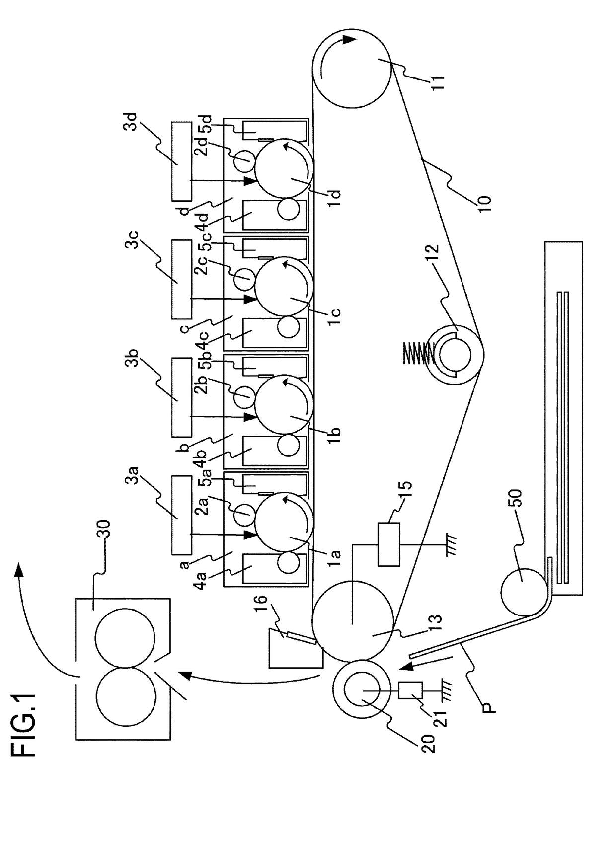
[0033]FIG. 1 is a schematic diagram of an image forming apparatus according to a first embodiment of the present invention. A description will be given, with reference to FIG. 1, of the configurations and the operations of the image forming apparatus of the embodiment. Examples of an image forming apparatus to which the present invention is applicable include a copier and a printer using an electrophotographic system. Here, a case in which the present invention is applied to a color laser printer will be described. Note that the image forming apparatus of the embodiment is a so-called tandem type printer having a plurality of image forming stations a to d. A first image forming station a forms an image of yellow (Y), a second image forming station b forms an image of magenta (M), a third image forming station c forms an image of cyan (C), and a fourth image forming station d forms an image of black (Bk). The configurations of the respective image forming stations are the same except...

second embodiment

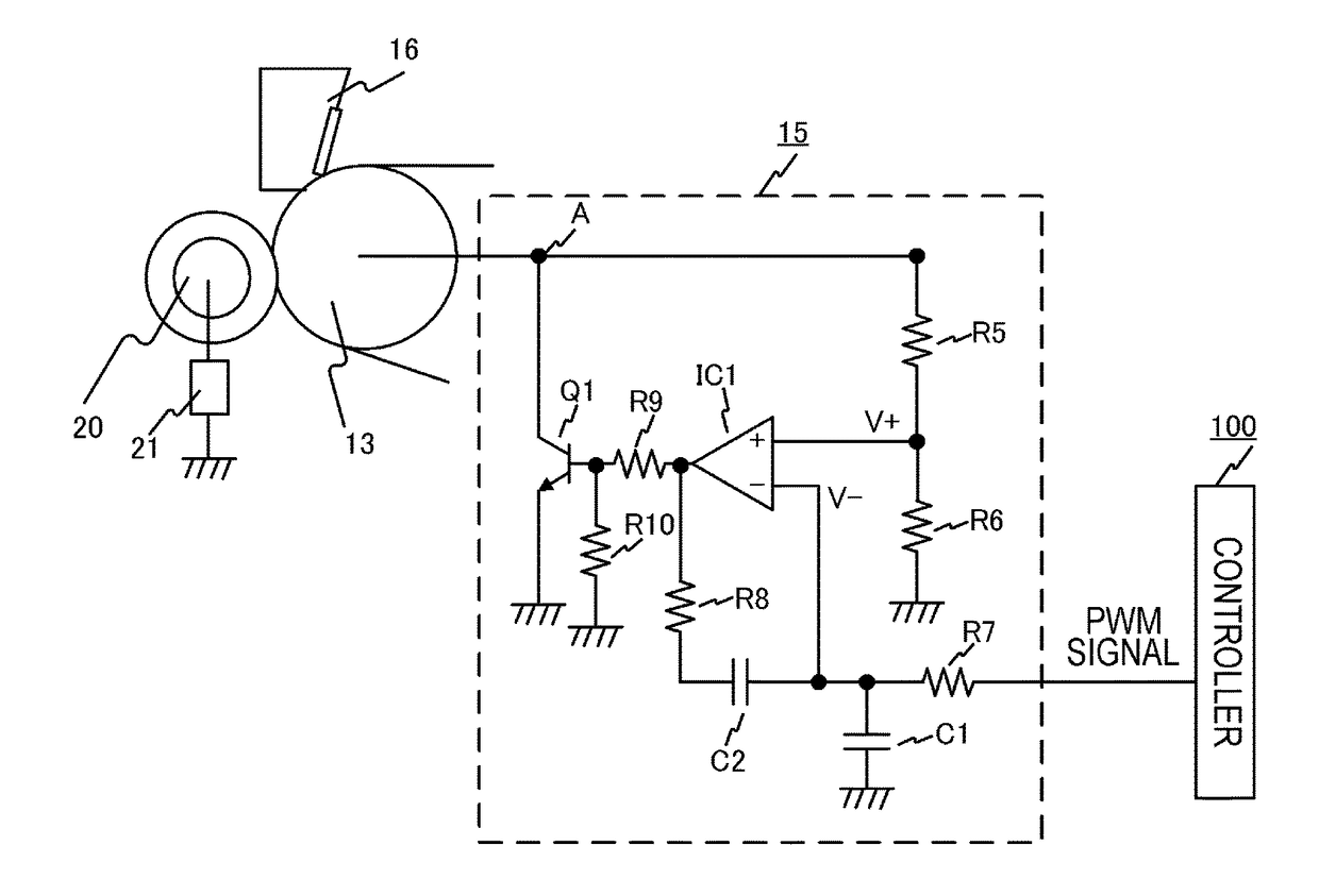
[0060]A description will be given, with reference to FIGS. 9 and 10, of an image forming apparatus according to a second embodiment of the present invention. In the image forming apparatus according to the second embodiment, the same configurations as those of the first embodiment will be denoted by the same symbols, and their descriptions will be omitted. FIG. 9 is a schematic diagram of the image forming apparatus according to the second embodiment of the present invention, and FIG. 10 is a diagram for describing the circuit configuration of a primary transfer portion in the second embodiment of the present invention.

[0061]As shown in FIG. 9, transfer rollers 14a, 14b, 14c, and 14d serving not only as primary transfer members but also as contact members are arranged at positions opposing photosensitive drums 1a, 1b, 1c, and 1d, respectively, via an intermediate transfer belt 10 in the configuration of the embodiment. Further, a secondary transfer opposing roller 13 by which the in...

third embodiment

[0069]FIG. 11 is a schematic diagram of an image forming apparatus according to a third embodiment of the present invention. In the description of the embodiment, first to fourth image forming stations will be denoted by symbols 70a to 70d, photosensitive drums will be denoted by symbols 700a to 700d, an intermediate transfer belt will be denoted by symbol 600, a driving roller will be denoted by symbol 603c, a tension roller will be denoted by symbol 603b, a secondary transfer opposing roller will be denoted by symbol 603a, and a secondary transfer roller will be denoted by symbol 601. Other than these components, the same configurations as those of the first and second embodiments will be denoted by the same symbols, and their descriptions will be omitted in the image forming apparatus according to the third embodiment. In the third embodiment, matters that will not be particularly described are the same as those of the first and second embodiments. Note that the image forming app...


PUM


Abstract

An image forming apparatus includes a voltage adjustment portion having a voltage adjustment member connected to a contact member contacting an endless belt, the voltage adjustment portion changing a current flowing from a current supply member contacting the belt at a position different from a position, at which an image bearing member contacts the belt in a rotating direction of the belt, to the voltage adjustment member via the belt according to a control signal input from a control portion outputting a control signal, thereby changing a size of a transfer potential—a surface potential—to transfer a toner image borne by the image bearing member onto the belt at a part at which the belt contacts the image bearing member.

Description

BACKGROUND OF THE INVENTIONField of the Invention[0001]The present invention relates to an image forming apparatus using an electrophotographic system.Description of the Related Art[0002]Conventionally, there has been known an image forming apparatus such as a copier and a laser beam printer configured to use an endless belt as an intermediate transfer member. In the image forming apparatus, a toner image formed on the surface of a photosensitive drum serving as an image bearing member is transferred onto a belt as a primary transfer step when a voltage is applied from a voltage power supply to a primary transfer member arranged at a part opposing the photosensitive drum. Then, the primary transfer step is repeatedly performed with respect to toner images of a plurality of colors to form the toner images of the plurality of colors on the surface of the belt. Subsequently, the toner images of the plurality of colors formed on the surface of the belt are collectively transferred onto ...

Claims


Application Information

Patent Timeline
Patent Type & Authority Applications(United States)
IPC IPC(8): G03G15/16
CPCG03G15/0194G03G15/0121G03G15/80G03G21/168G03G15/1615G03G21/1652G03G15/1605G03G15/0189G03G15/1675
Inventor SAITO, SEIJIISHIZUMI, KEISUKETAKAYAMA, TOSHIHIKOOHNO, MASARUITO, SHINGOISHIO, SHOHEISAMEJIMA, KEISUKEKOJIMA, KEIZOMATSUMURA, RYO
Owner CANON KK
Why Eureka
Try Eureka