Electromagnetic relay

a technology of electromagnetic relays and relays, applied in electromagnetic relay details, contact, electrical equipment, etc., can solve the problems of reducing the energization performance, reducing the coil capacity, and reducing the drive performance of contact terminals, so as to reduce the thickness of retaining portions, reduce the thickness and reduce the size of fixed contact terminals and backstops serving as current carrying paths

Active Publication Date: 2011-05-26
EM DEVICES CORP
View PDF4 Cites 9 Cited by
  • Summary
  • Abstract
  • Description
  • Claims
  • Application Information

AI Technical Summary

Benefits of technology

[0023]As described above, in the present invention, the fixed contact terminal retaining portions and backstop retaining portion retain the two fixed contact terminals and backstop respectively. The fixed contact terminal retaining portions are provided outside a projection obtained by perpendicularly projecting the movable contact spring on the surface of the base block so as to sandwich the part of the movable contact spring that extends from the base portion thereof toward the contact point. The backstop retaining portion retains the backstop at the portion outside the projection and opposite to the base portion of the movable contact spring. That is, in the case where the base block has rectangular shape, the above retaining portions are distributed to three different portions: left and right side portions of the base portion; and a portion along one side of the base portion which is positioned between the left and right side portions. Thus, sufficient spaces can be ensured between the two fixed contact terminals and between each of the fixed contact terminals and backstop, whereby a sufficient insulation distance can be ensured without providing a partition using the protrusion and the like adopted in Patent Document 1 and whereby the sizes of the fixed contact terminals and backstop each serving as a current carrying path can be increased.
[0024]The width directions of plates constituting the fixed contact terminals and width direction of a plate constituting the backstop are made substantially parallel to the left and right sides of the base plate of the base block having the fixed contact terminal retaining portions and backstop retaining portion and portion along one side of the base portion which is positioned between the left and right side portions. With this configuration, it is possible to reduce the thicknesses of the retaining portions, which in turn increases the coil winding width to thereby improve contact drive performance while maintaining the miniaturization.
[0025]The fixed contact terminals and backstop are fixed not to the flange portion of the coil bobbin, but to the fixed contact terminal retaining portions and backstop retaining portions provided in the base block. This means that members subject to heat of the coil and heat generated due to conduction between the contact terminals are separated from each other. Thus, even if a failure occurs while the movable contact and make fixed contact are being connected, there is no possibility of occurrence of a failure mode, as observed in the conventional approach, in which the flange portion is melt to cause the movable contact and fixed contact to be firmly fixed to each other while they are being connected to lead to malfunction in which current is not cut off but continues to flow. Further, since a structure in which the fixed contact terminals and backstop are press-fit and retained near the movable contacts or fixed contacts is not adopted, it is possible to avoid occurrence of electric contact trouble due to cutting scrap, etc.
[0026]As described above, according to the present invention, there can be provided an electromagnetic relay having a reduced size, high conductivity, a high insulating performance between the two fixed contact terminals and between each of the fixed contact terminals and backstop, a small number of factors causing a failure, and high reliability of electric contact.

Problems solved by technology

Meanwhile, along with miniaturization of the electromagnetic relay, problems such as a reduction in contact drive performance due to a reduction in the coil capacity, a reduction in energization performance due to an increase of resistance of a current carrying path in the electromagnetic relay, and a reduction in insulation performance due to a reduction in the distance between terminals are arisen, a further improvement is required for these performances.

Method used


Image

  • Electromagnetic relay
  • Electromagnetic relay
  • Electromagnetic relay

Examples


Embodiment Construction

[0032]Embodiments of the present invention will be described below with reference to the accompanying drawings.

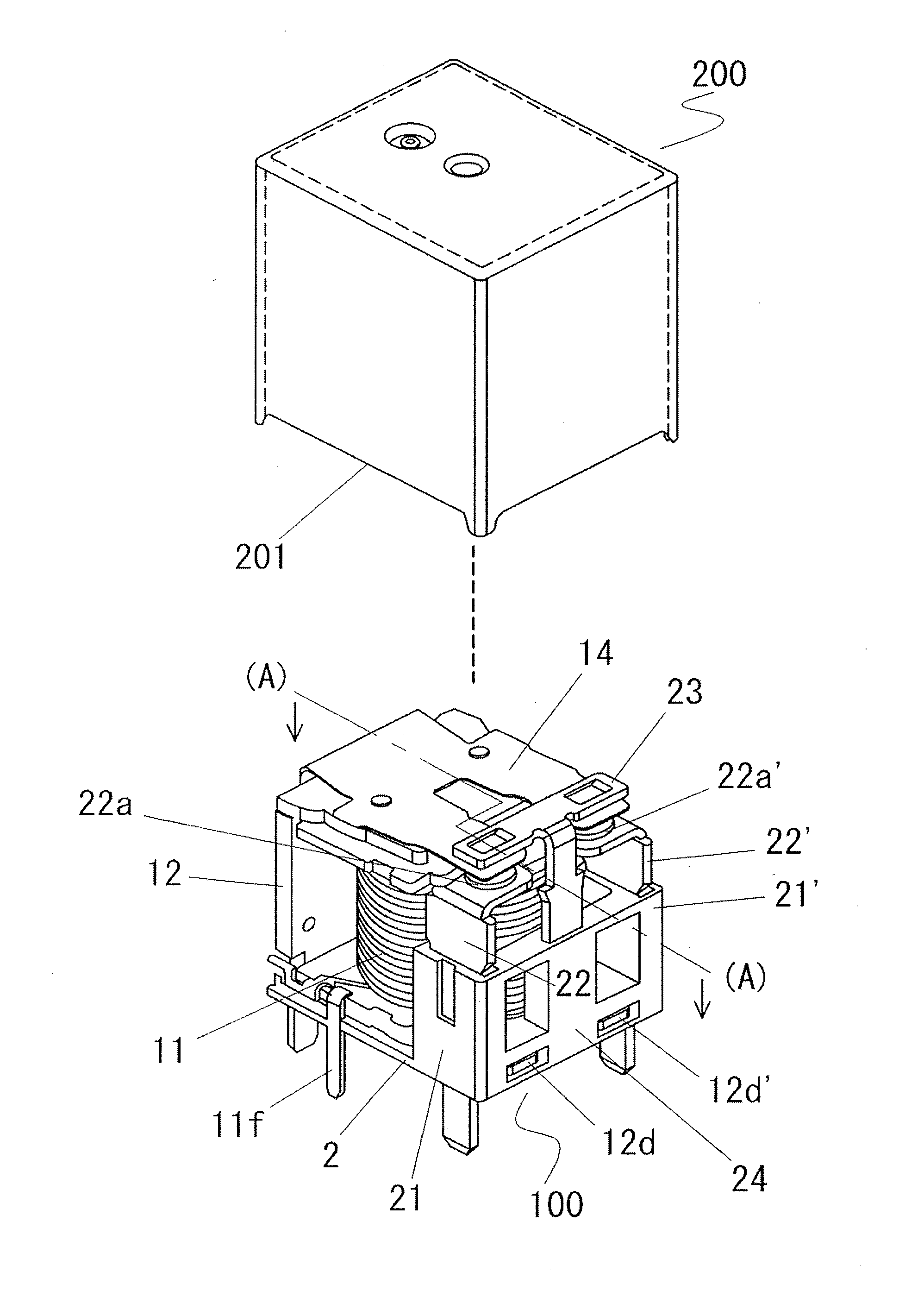
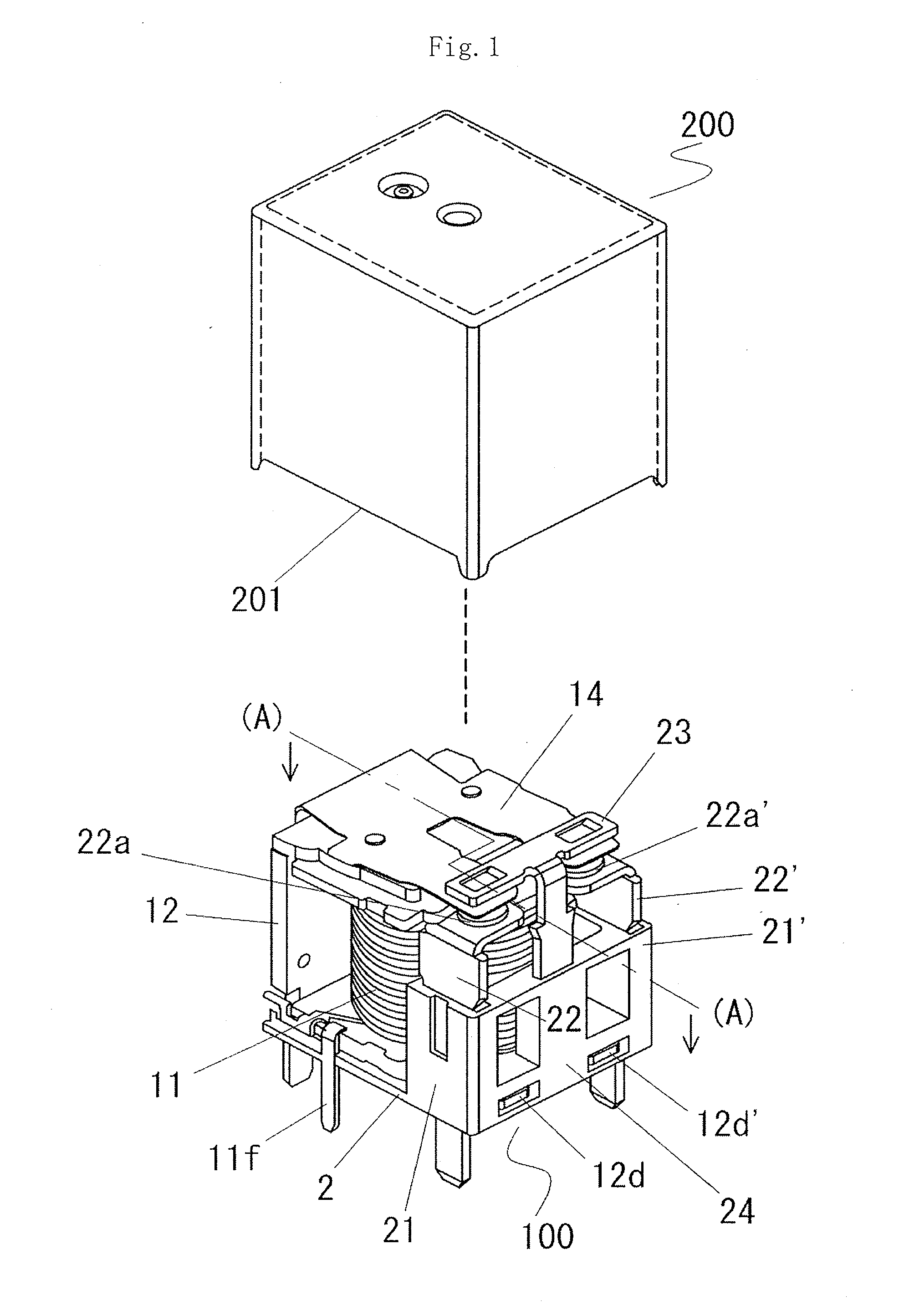
[0033]FIG. 1 illustrates an embodiment of an electromagnetic relay according to the present invention, which is a perspective view of a cover of an electromagnetic relay body and the electromagnetic relay body from which the cover is removed. FIG. 2 is a cross-sectional view of the electromagnetic relay, taken along (A)-(A) line of FIG. 1, and FIG. 3 is an exploded perspective view of the electromagnetic relay body of FIG. 1.

[0034]As illustrated in FIGS. 1 and 2, the electromagnetic relay in the present embodiment includes an electromagnetic relay body 100 and a cover 200 for covering the electromagnetic relay body 100. The electromagnetic relay body 100 includes an electromagnetic block 1 having a coil and a movable contact spring 14 swung by current flowing through the coil, two fixed contact terminals 22 and 22′ having fixed contacts 22a and 22a′ respectively, a backstop...


PUM


Abstract

To provide an electromagnetic relay having a reduced size, high conductivity, a high insulating performance between two fixed contact terminals and between each of the fixed contact terminals and backstop, a small number of factors causing a failure, and high reliability of electric contact.
An electromagnetic relay has an electromagnetic block provided with a movable contact spring 14 swung by current flowing in a coil, two fixed contact terminals 22 and 22′ each having a fixed contact, a backstop 23 having two movable contact abutment portions, and a base block 2 for retaining the above components. The base block 2 has a base portion 20 having substantially a rectangular shape, fixed contact terminal retaining portions 21 and 21′ extending vertically from two opposing sides of the rectangle so as to retain the two fixed contact terminals, and a backstop retaining portion 24 extending vertically from the center portion of one of the remaining two opposing sides of the rectangle.

Description

TECHNICAL FIELD[0001]The present invention relates to an electromagnetic relay mounted on a printed circuit board, etc., as an electric component for, e.g., an automobile.BACKGROUND ART[0002]Along with an increase in the mounting rate of electric components mounted in an automobile, miniaturization and high-density packaging of electric devices mounted in an automobile are proceeding, and miniaturization is also required for an electromagnetic relay mounted in such an electric device. Meanwhile, along with miniaturization of the electromagnetic relay, problems such as a reduction in contact drive performance due to a reduction in the coil capacity, a reduction in energization performance due to an increase of resistance of a current carrying path in the electromagnetic relay, and a reduction in insulation performance due to a reduction in the distance between terminals are arisen, a further improvement is required for these performances. An improvement in contact stability between c...

Claims


Application Information

Patent Timeline
Patent Type & Authority Applications(United States)
IPC IPC(8): H01H50/00
CPCH01H1/2066H01H50/026H01H50/043H01H50/14H01H50/56H01H50/60H01H2050/028H01H50/546H01H50/28
Inventor KOJIMA, KATSUTOCHIBA, KEIMUTOU, KOUICHI
Owner EM DEVICES CORP
Why Eureka
Try Eureka