Optical image capturing system

a technology of optical image and capturing system, which is applied in the field of optical image capturing system, can solve the problems of increasing imaging distortion, difficult manufacturing process, and poor peripheral imaging quality, and achieve the effect of fine tuning and correction, and shortening the back focal length

Inactive Publication Date: 2016-03-17
ABILITY OPTO ELECTRONICS TECH
View PDF1 Cites 7 Cited by
  • Summary
  • Abstract
  • Description
  • Claims
  • Application Information

AI Technical Summary

Benefits of technology

[0024]When |f / f1| satisfies with the preceding conditions, displacement of the first lens' refractive power is better and is able to avoid causing large aberration such that cannot be corrected, and when in the condition of |f2|+|f3|+|f4|+f5|>|f1|+|f6|, it uses at least one of the second lens to the fifth lens that has weak positive refractive power or weak negative refractive power. The so-called weak refractive power means that the absolute value of focal length of the specific lens is larger than 10. When at least one of the second lens to the fifth lens of the present invention has weak positive refractive power, it may be able to share the positive refractive power of the first lens so as to avoid the unnecessary aberration occurring too early; to the contrary, if at least one of the second lens to the fifth lens of the present invention has weak negative refractive power, the aberration of the system can thereby be fine-tuned and corrected.
[0025]The sixth lens may have negative refractive power, and the image-side surface thereof may be a concave surface which may benefit from shortening the back focal length to maintain the miniaturization. Additionally, at least one surface of the sixth lens may have at least one inflection point which is able to suppress the incident angle of the light in off-axis field of view so that the caused aberration can be corrected.

Problems solved by technology

However, the optical system with larger aperture often encounters situations pertaining to obstacles to more aberrations leading to a worse peripheral imaging quality and difficulty in manufacturing process, and design of the optical system with wild field of view has technical problem of increasing imaging distortion.
As a result, the known optical image capturing system is not able to satisfy with a higher level demand of photography anymore.
Therefore, besides further promoting quality of the total image pixels as well as giving consideration to the balanced design of microminiaturization optical image capturing lens, how to boost the exposure value of optical image capturing lens and widen the field of view thereof has become a crucial issue.

Method used


Image

  • Optical image capturing system
  • Optical image capturing system
  • Optical image capturing system

Examples


first embodiment

The First Embodiment

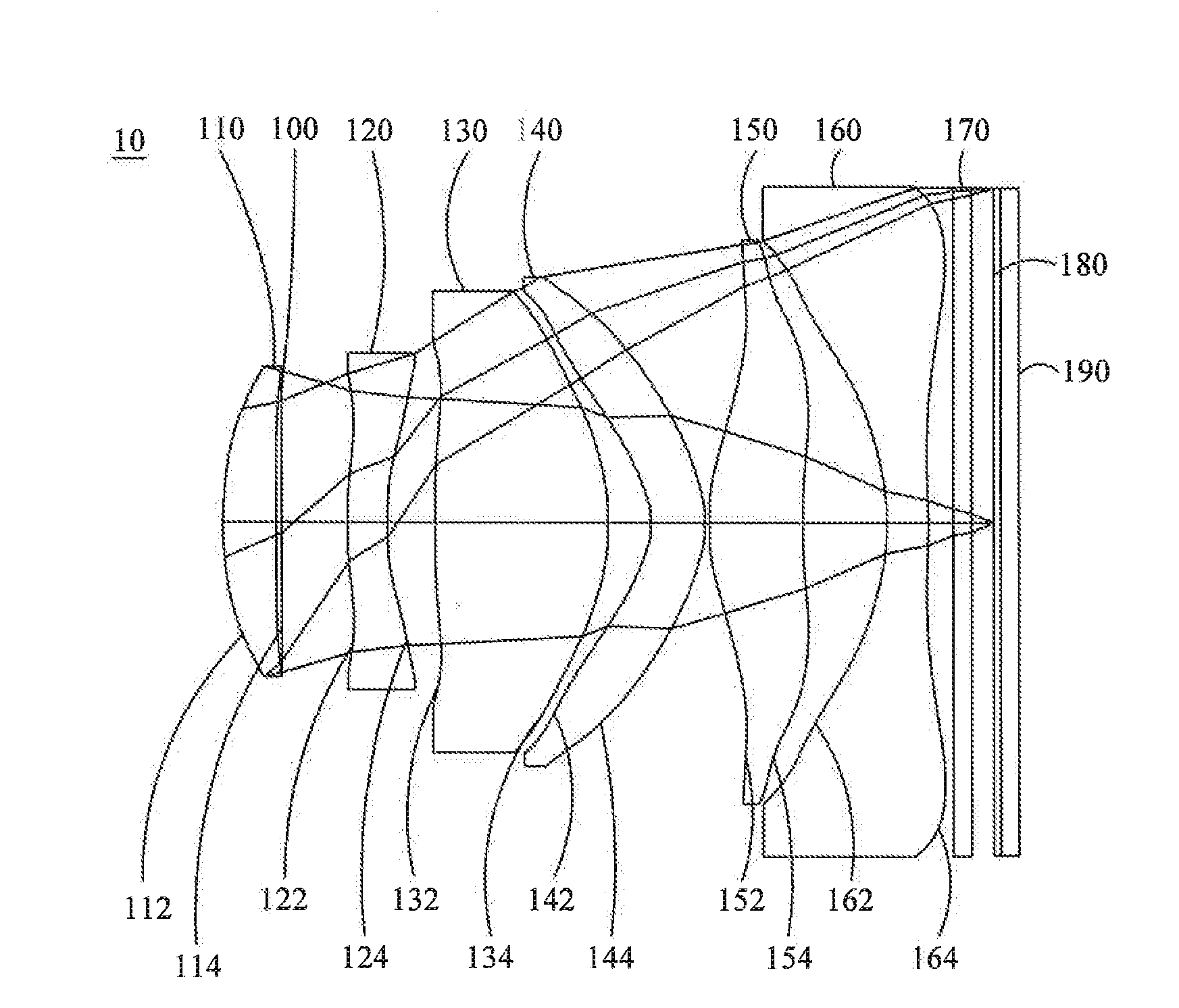
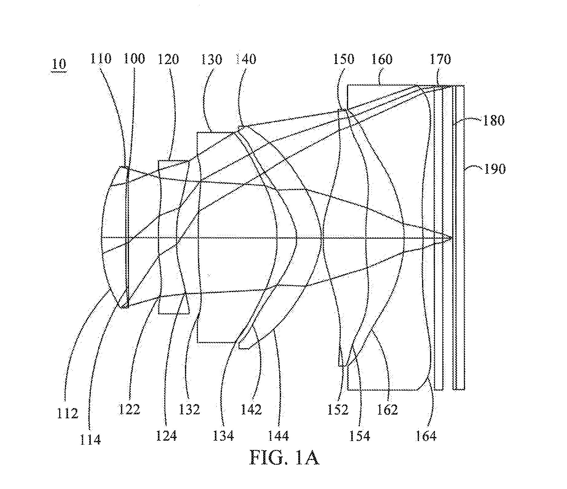
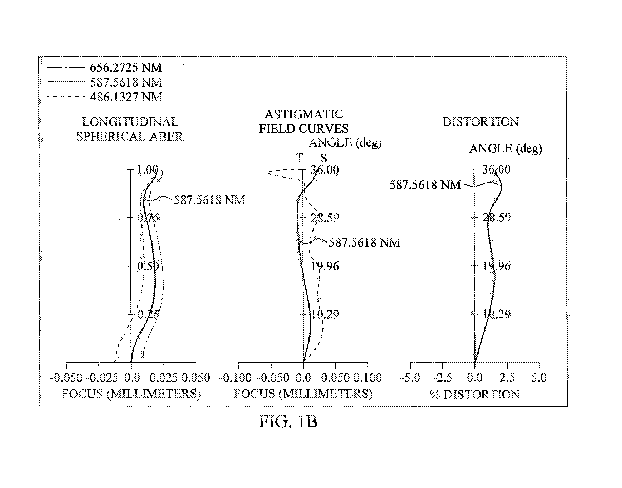
[0079]Please refer to FIGS. 1A and 1B which are a schematic diagram of the first embodiment of an optical image capturing system according to the present invention and curve diagrams of longitudinal spherical aberration, astigmatic field curves and optical distortion of the first embodiment of an optical image capturing system according to the present invention from left to right respectively. FIG. 1C is a diagram of TV distortion grid of the first embodiment of an optical image capturing system according to the present invention. It can be found through FIG. 1A that the optical image capturing system, in order from an object side to an image side comprises a first lens 110, an aperture 100, a second lens 120, a third lens 130, a fourth lens 140, a fifth lens 150, a sixth lens 160, an IR filter 170, an image-plane 180 and an image sensing device 190.

[0080]The first lens 110 has positive refractive power, and is made of plastic; object-side surface 112 is convex a...

second embodiment

The Second Embodiment

[0115]Please refer to FIGS. 2A, and 2B which are a schematic diagram of the second embodiment of an optical image capturing system according to the present invention and curve diagrams of longitudinal spherical aberration, astigmatic field curves and optical distortion of the second embodiment of an optical image capturing system according to the present invention from left to right, respectively. FIG. 2C is a curve diagram of TV distortion grid of the second embodiment of an optical image capturing system according to the present invention. It can be found through FIG. 2A that the optical image capturing system, in order from an object side to an image side comprises an aperture 200, a first lens 210, a second lens 220, a third lens 230, a fourth lens 240, a fifth lens 250, a sixth lens 260, an IR filter 270, an image-plane 280 and an image sensing device 290.

[0116]The first lens 210 has positive refractive power, and is made of plastic; object-side surface 212...

third embodiment

The Third Embodiment

[0131]Please refer to FIGS. 3A and 3B which are a schematic diagram of the third embodiment of an optical image capturing system according to the present invention and curve diagrams of longitudinal spherical aberration, astigmatic field curves and optical distortion of the third embodiment of an optical image capturing system according to the present invention from left to right, respectively. FIG. 3C is a curve diagram of TV distortion grid of the third embodiment of an optical image capturing system according to the present invention. It can be found through FIG. 3A that the optical image capturing system, in order from an object side to an image side comprises an aperture 300, a first lens 310, a second lens 320, a third lens 330, a fourth lens 340, a fifth lens 350, a sixth lens 360, an IR filter 370, an image-plane 380 and an image sensing device 390.

[0132]The first lens 310 has positive refractive power, and is made of plastic; object-side surface 312 is c...


PUM


Abstract

A six-piece optical lens for capturing image and a six-piece optical module for capturing image are provided. In order from an object side to an image side, the optical lens along the optical axis comprises a first lens with positive refractive power having a convex object-side surface; a second lens with refractive power, a third lens with refractive power; a fourth lens with refractive power; a fifth lens with refractive power; and a sixth lens with negative refractive power; the sixth lens has a concave image-side surface and at least one of the image-side surface and an object-side surface has inflection point, and both surfaces are aspheric. The optical lens can increase aperture value and improve the imagining quality for use in compact cameras.

Description

CROSS-REFERENCE TO RELATED APPLICATION[0001]This application claims priority from Taiwan Patent Application No. 103131572, filed on Sep. 12, 2014, in the Taiwan Intellectual Property Office, the content of which are hereby incorporated by reference in their entirety for all purposes.BACKGROUND OF THE INVENTION[0002]1. Field of the Invention[0003]The present invention relates to an optical image capturing system, in particular with respect to a miniaturized optical image capturing system applied to electronic product.[0004]2. Description of the Related Art[0005]Recently, with the thriving and robust of portable electronic product having recording function needs for optical system increase gradually. The charge coupled device of general optical system is nothing else but charge coupled device (CCD) or complementary metal-oxide semiconductor sensor (CMOS sensor), and with the burgeoning development of semiconductor manufacturing process, pixel size of charge coupled device shortens, an...

Claims


Application Information

Patent Timeline
Patent Type & Authority Applications(United States)
IPC IPC(8): G02B13/00G02B9/62H04N5/225
CPCG02B13/0045H04N5/225G02B9/62
Inventor TANG, NAI-YUANCHANG, YEONG-MING
Owner ABILITY OPTO ELECTRONICS TECH
Why Eureka
Try Eureka