Thin film balun
- Summary
- Abstract
- Description
- Claims
- Application Information
AI Technical Summary
Benefits of technology
Problems solved by technology
Method used
Image
Examples
example 1a
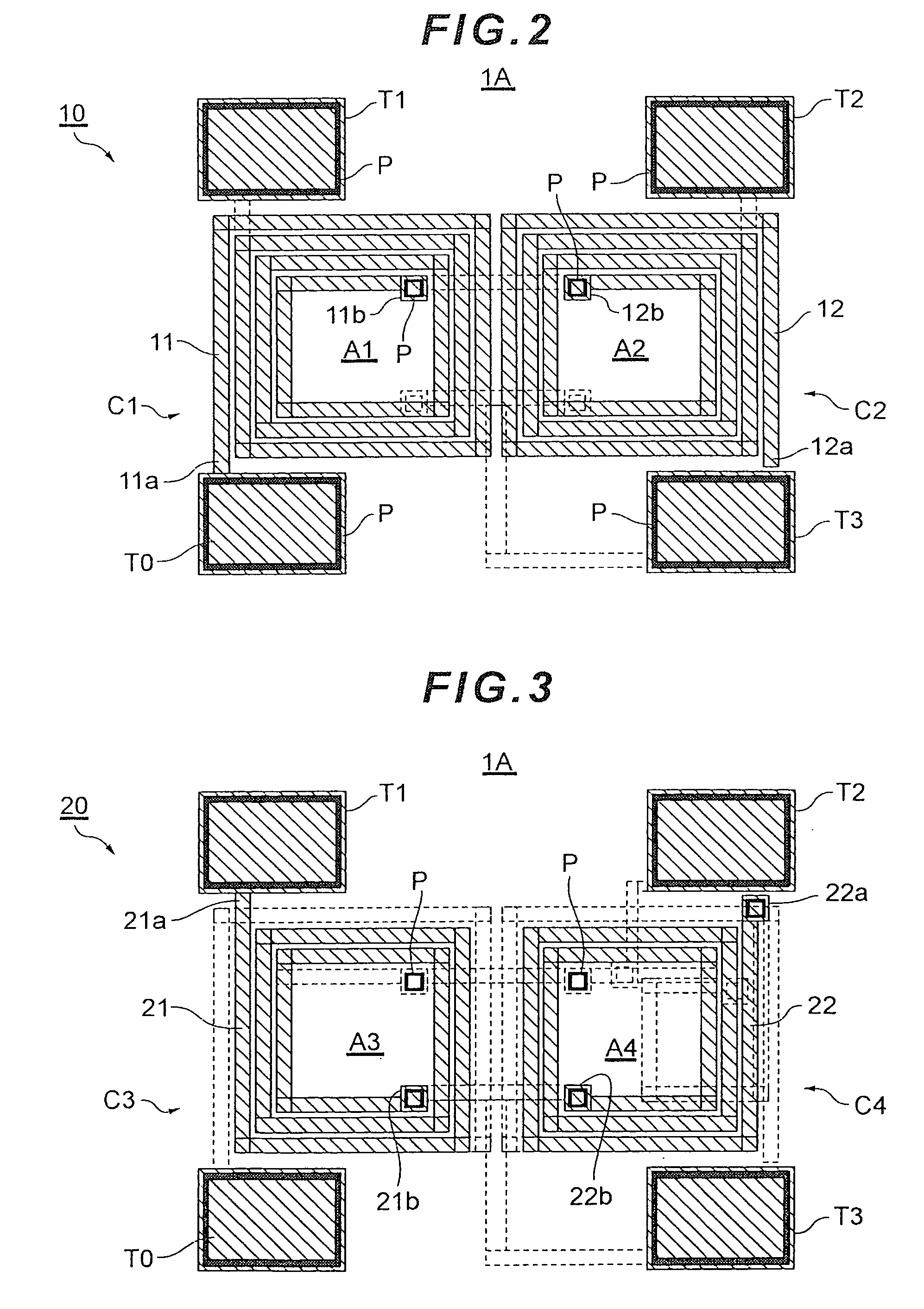
[0068]FIGS. 2 to 6 are plan views of individual wiring layers of a thin film balun 1A in an example 1A. In detail, FIG. 2 is a plan view of a first wiring layer 10, FIG. 3 is a plan view of a second wiring layer 20, FIG. 4 is a plan view of a third wiring layer 30, FIG. 5 is a plan view of a fourth wiring layer 40, and FIG. 6 is a plan view of a fifth wiring layer 50. The first wiring layer 10 is a lowermost wiring layer, and the fifth wiring layer 50 is an uppermost wiring layer. A substrate is located under the first wiring layer 10 which is the lowermost layer, though not shown in the drawings. That is, the thin film balun is formed on the substrate.
[0069]As shown in FIGS. 2 to 6, the unbalanced terminal T0, the first balanced terminal T1, the second balanced terminal T2, and a ground terminal T3 are formed on all layers of the first wiring layer 10 to the fifth wiring layer 50. Each of the terminals T0 to T3 is electrically connected between different layers via a through hole P...
example 1b
[0080]In an example 1B, the auxiliary coil portion C5 is positioned so as not to overlap the coil openings and the coil conductors of the first coil portion C1 and the second coil portion C2. FIGS. 7 and 8 are plan views respectively showing the fourth wiring layer 40 and the fifth wiring layer 50 of a thin film balun 1B in the example 1B. Note that the first wiring layer 10 to the third wiring layer 30 of the thin film balun 1B in the example 1B have the same structures as the example 1A.
[0081]As shown in FIGS. 7 and 8, the auxiliary coil portion C5 is constituted by a coil conductor 43 of the fourth wiring layer 40 and a coil conductor 52 of the fifth wiring layer 50. One end of the coil conductor 43 is connected to one end of the coil conductor 52 via a through hole P, and the other end of the coil conductor 43 is connected to the end 22a of the coil conductor 22 constituting the fourth coil portion C4 via a through hole P. The other end 52a of the coil conductor 52 is connected ...
example 1f
[0096]In the example 1F, the auxiliary coil portion C5 is formed by the third wiring layer 30 and the fourth wiring layer 40. FIGS. 16 and 17 are plan views respectively showing the third wiring layer 30 and the fourth wiring layer 40 of a thin film balun 1F in the example 1F. Note that the first wiring layer 10 and the second wiring layer 20 of the thin film balun 1F in the example 1F have the same structures as the example 1A. In addition, the fifth wiring layer 50 of the example 1A is unnecessary in the example 1F.
[0097]As shown in FIGS. 16 and 17, the auxiliary coil portion C5 is constituted by coil conductors 33, 34, and 48 of the third wiring layer 30 and the fourth wiring layer 40. Connection relationships of the coil conductors 33, 34, and 48 are the same as the coil conductors 41, 42, and 51 in the example 1A.
[0098]In the example 1F, the auxiliary coil portion C5 is positioned in an area facing the coil conductors of the second coil portion C2 and the fourth coil portion C4...
PUM
 Abstract
Description
Claims
Application Information
 - R&D
- Intellectual Property
- Life Sciences
- Materials
- Tech Scout
- Unparalleled Data Quality
- Higher Quality Content
- 60% Fewer Hallucinations
Browse by: Latest US Patents, China's latest patents, Technical Efficacy Thesaurus, Application Domain, Technology Topic, Popular Technical Reports.
© 2025 PatSnap. All rights reserved.Legal|Privacy policy|Modern Slavery Act Transparency Statement|Sitemap|About US| Contact US: help@patsnap.com


