Power storage apparatus, method for controlling power storage apparatus, and vehicle
- Summary
- Abstract
- Description
- Claims
- Application Information
AI Technical Summary
Benefits of technology
Problems solved by technology
Method used
Image

Examples
embodiment 1
[0035]Embodiment 1 of the present invention will be described with FIGS. 1 to 8.
[0036]1. Description of Battery
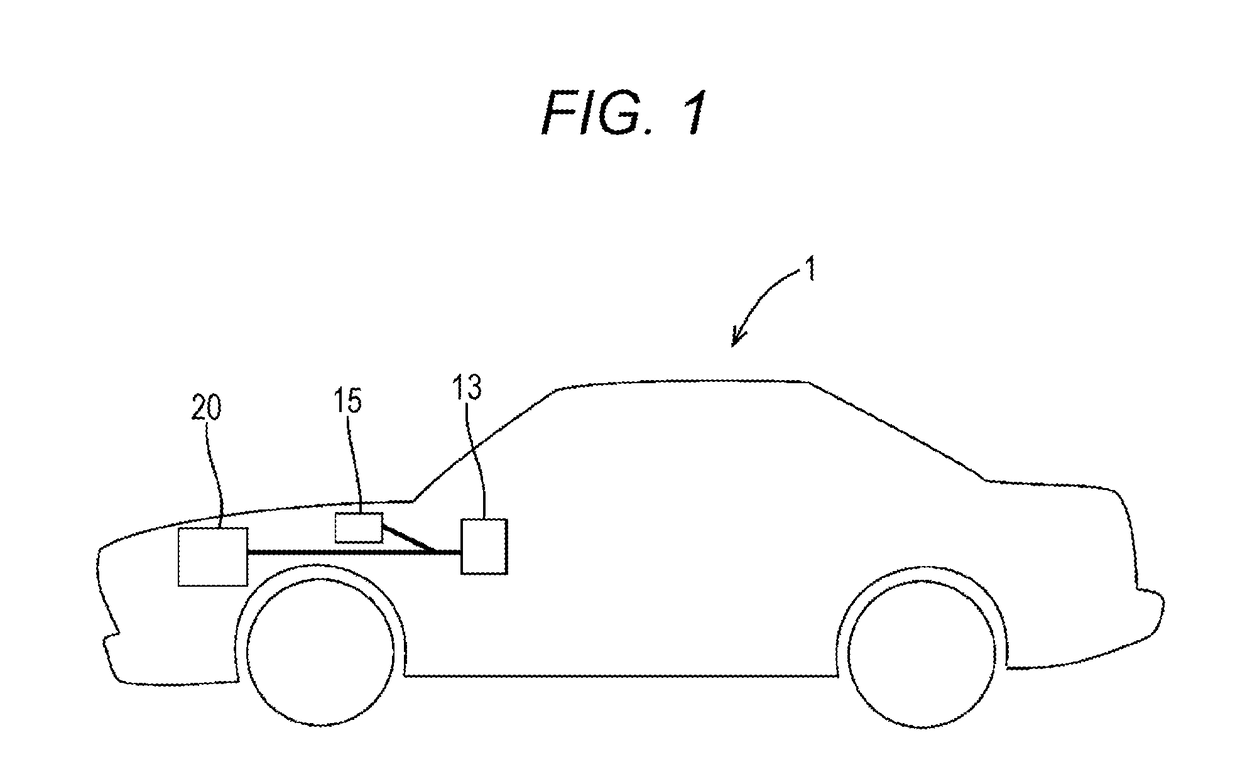
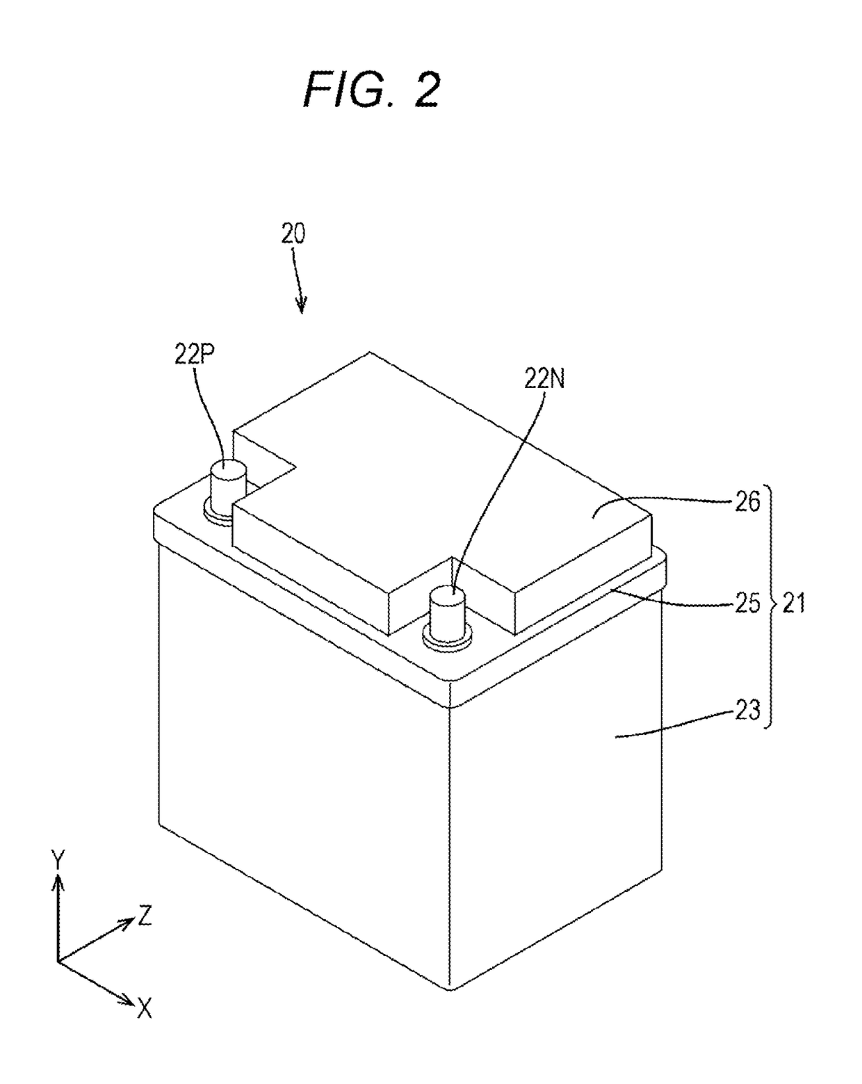
[0037]FIG. 1 is a side view of a vehicle; FIG. 2 is a perspective view of a battery; and FIG. 3 is an exploded perspective view of the battery.
[0038]As shown in FIG. 1, a vehicle 1 includes an electronic control device 13, an alternator 15, and a battery 20. Although not shown in FIG. 1, the vehicle 1 is provided with a vehicle load 10, such as an air conditioner and a headlamp, other than the electronic control device 13. The battery 20 corresponds to a “power storage apparatus”, and the alternator 15 corresponds to a “vehicle generator”.
[0039]The battery 20 supplies electric power to the vehicle load 10 including the electronic control device 13, and is connected to the alternator 15 controlled by the electronic control device 13. The alternator 15 includes an adjusting unit (not shown) that adjusts an output, and is subjected to feedback control so that an output voltage...
embodiment 2
[0093]Subsequently, Embodiment 2 of the present invention will be described with FIG. 9.
[0094]In Embodiment 1, there is described an example in which during the switching control, the duty ratio of the semiconductor switch Q1 is 50% that is a fixed value. In Embodiment 2, the duty ratio Dy of the semiconductor switch Q1 is switched according to the highest voltage Vm of the secondary batteries 31.
[0095]Specifically, as shown in FIG. 9, when the highest voltage Vm of the secondary batteries 31 is 3.7 V to 3.8 V, the duty ratio Dy of the semiconductor switch Q1 is 50%; when the highest voltage Vm of the secondary batteries 31 is 3.8 V to 3.9 V, the duty ratio Dy of the semiconductor switch Q1 is 30%; and when the highest voltage Vm of the secondary batteries 31 is 3.9 V to 4.0 V, the duty ratio Dy of the semiconductor switch Q1 is 10%.
[0096]In this way, the duty ratio Dy of the semiconductor switch Q1 is switched to be smaller as the highest voltage Vm of the secondary batteries 31 be...
embodiment 3
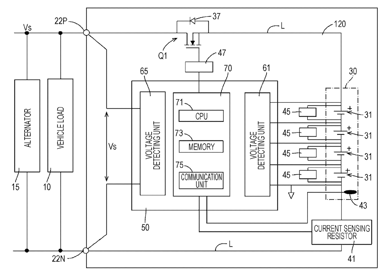
[0097]Subsequently, Embodiment 3 of the present invention will be described with FIGS. 10 to 12. FIG. 10 is a block diagram showing an electrical configuration of a battery 120 in Embodiment 3. FIG. 11 is a flowchart showing the flow of an output suppressing process.
[0098]In Embodiment 1, there is described an example in which when the highest voltage Vm of the secondary batteries 31 exceeds the first voltage (3.7 V as an example) during the charge, the semiconductor switch Q1 is switched from a conducting state to a switching state where the semiconductor switch Q1 is alternately turned on and off with a predetermined period.
[0099]If the semiconductor switch Q1 is switched to the switching control during the charge, while the semiconductor switch Q1 is turned off, the battery 20 is disconnected from the alternator 15. Accordingly, the load on the alternator 15 is reduced by a load from the battery, and therefore the output voltage tends to rise. By adjusting the field current flowi...
PUM
 Abstract
Description
Claims
Application Information
 - R&D
- Intellectual Property
- Life Sciences
- Materials
- Tech Scout
- Unparalleled Data Quality
- Higher Quality Content
- 60% Fewer Hallucinations
Browse by: Latest US Patents, China's latest patents, Technical Efficacy Thesaurus, Application Domain, Technology Topic, Popular Technical Reports.
© 2025 PatSnap. All rights reserved.Legal|Privacy policy|Modern Slavery Act Transparency Statement|Sitemap|About US| Contact US: help@patsnap.com