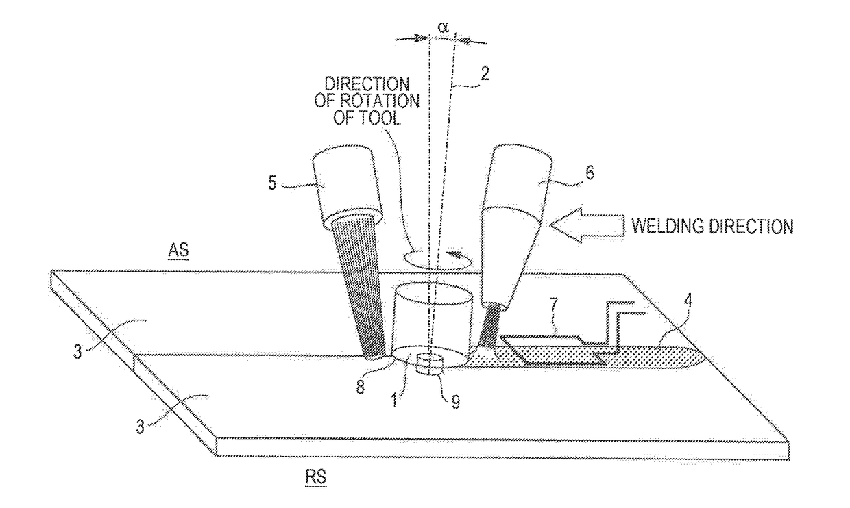
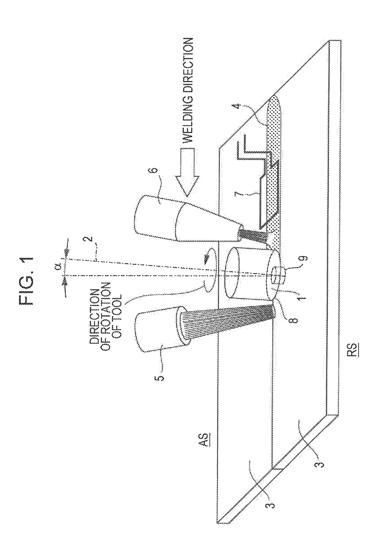
Friction stir welding apparatus for structural steel
a friction stir welding and structural steel technology, applied in the direction of soldering apparatus, welding devices, manufacturing tools, etc., can solve the problems of increasing welding speed, affecting the use of friction stir welding methods for structural steel, and limiting the shape and dimensions of metal materials to be welded, so as to reduce microstructure changes, improve welding workability, and high joint strength
- Summary
- Abstract
- Description
- Claims
- Application Information
AI Technical Summary
Benefits of technology
Problems solved by technology
Method used
Image
Examples
example 1
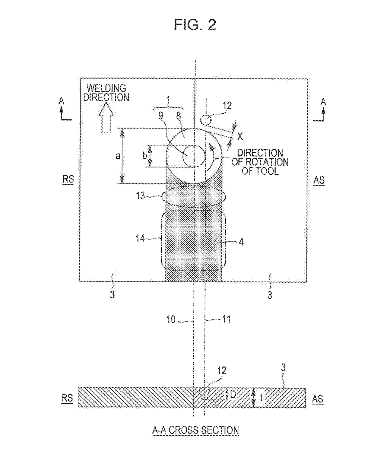
[0090]Friction stir welding was performed using a steel sheet having a thickness of 1.6 mm and having the chemical composition and the tensile strength shown in Table 1. The joint abutting faces formed a non-angled square groove and were subjected to one-side one-pass welding while the surface conditions were similar to those after milling. The welding conditions for friction stir welding are shown in Table 2. A rotary tool made of tungsten carbide (WC) and having the cross-sectional dimensions shown in FIG. 4 (shoulder diameter a: 12 mm, maximum diameter b of pin: 4.0 mm, probe length c: 1.4 mm) was used. During welding, oxidation of the surface was prevented by shielding the welded part with argon gas.
TABLE 1Chemical Composition (mass %)Tensile Strength0.8 ×No.CSiMnPS(MPa)TA1 (° C.)10.30.210.690.0120.003101557720.160.070.690.0160.009420574
TABLE 2Inclined AngleRotation Speed (rpm) of(°) of ToolToolWelding Speed (mm / min)3400400
[0091]To determine the region heated by preheating using...
example 2
[0106]As in Example 1, friction stir welding was performed using a steel sheet having a thickness of 1.6 mm and having the chemical composition and the tensile strength shown in Table 1. The joint abutting faces formed a non-angled square groove and were subjected to one-side one-pass welding while the surface conditions were similar to those after milling. The welding conditions for friction stir welding are shown in Table 7. As in Example 1, a rotary tool made of tungsten carbide (WC) and having the cross-sectional dimensions shown in FIG. 4 (shoulder diameter a: 12 mm, maximum diameter b of pin: 4.0 mm, probe length c: 1.4 mm) was used. During welding, oxidation of the surface was prevented by shielding the welded part with argon gas.
TABLE 7Inclined AngleRotation Speed (rpm) of(°) of ToolToolWelding Speed (mm / min)36001000
[0107]To determine the region heated by preheating using a laser as a heat source before welding, steel sheet 1 shown in Table 1 was irradiated with a laser beam...
PUM
| Property | Measurement | Unit |
|---|---|---|
| Fraction | aaaaa | aaaaa |
| Fraction | aaaaa | aaaaa |
| Fraction | aaaaa | aaaaa |
Abstract
Description
Claims
Application Information
 - R&D
- Intellectual Property
- Life Sciences
- Materials
- Tech Scout
- Unparalleled Data Quality
- Higher Quality Content
- 60% Fewer Hallucinations
Browse by: Latest US Patents, China's latest patents, Technical Efficacy Thesaurus, Application Domain, Technology Topic, Popular Technical Reports.
© 2025 PatSnap. All rights reserved.Legal|Privacy policy|Modern Slavery Act Transparency Statement|Sitemap|About US| Contact US: help@patsnap.com


