Methods and systems for providing photovoltaic plant power feed-in

Inactive Publication Date: 2018-02-15
ROBERT BOSCH GMBH
View PDF5 Cites 5 Cited by
  • Summary
  • Abstract
  • Description
  • Claims
  • Application Information

AI Technical Summary

Benefits of technology

[0003]However, problems have arisen in attempting to realize such systems. Prior approaches have relied upon systems using complex, non-linear equations, which have proven to be time consuming and expensive to operate. Moreover, uncertainty in the power level generated by the energy generati

Problems solved by technology

Failure of the photovoltaic power plant to fulfil these requirements results in a penalty in the form of a reduction in payment from the electric energy transmission system for the energy feed-in.
However, problems have arisen in attempting to realize such systems.
Prior approaches have relied upon systems using complex, non-linear equations, which have proven to be time consuming and

Method used


Image

  • Methods and systems for providing photovoltaic plant power feed-in
  • Methods and systems for providing photovoltaic plant power feed-in
  • Methods and systems for providing photovoltaic plant power feed-in

Examples


Example

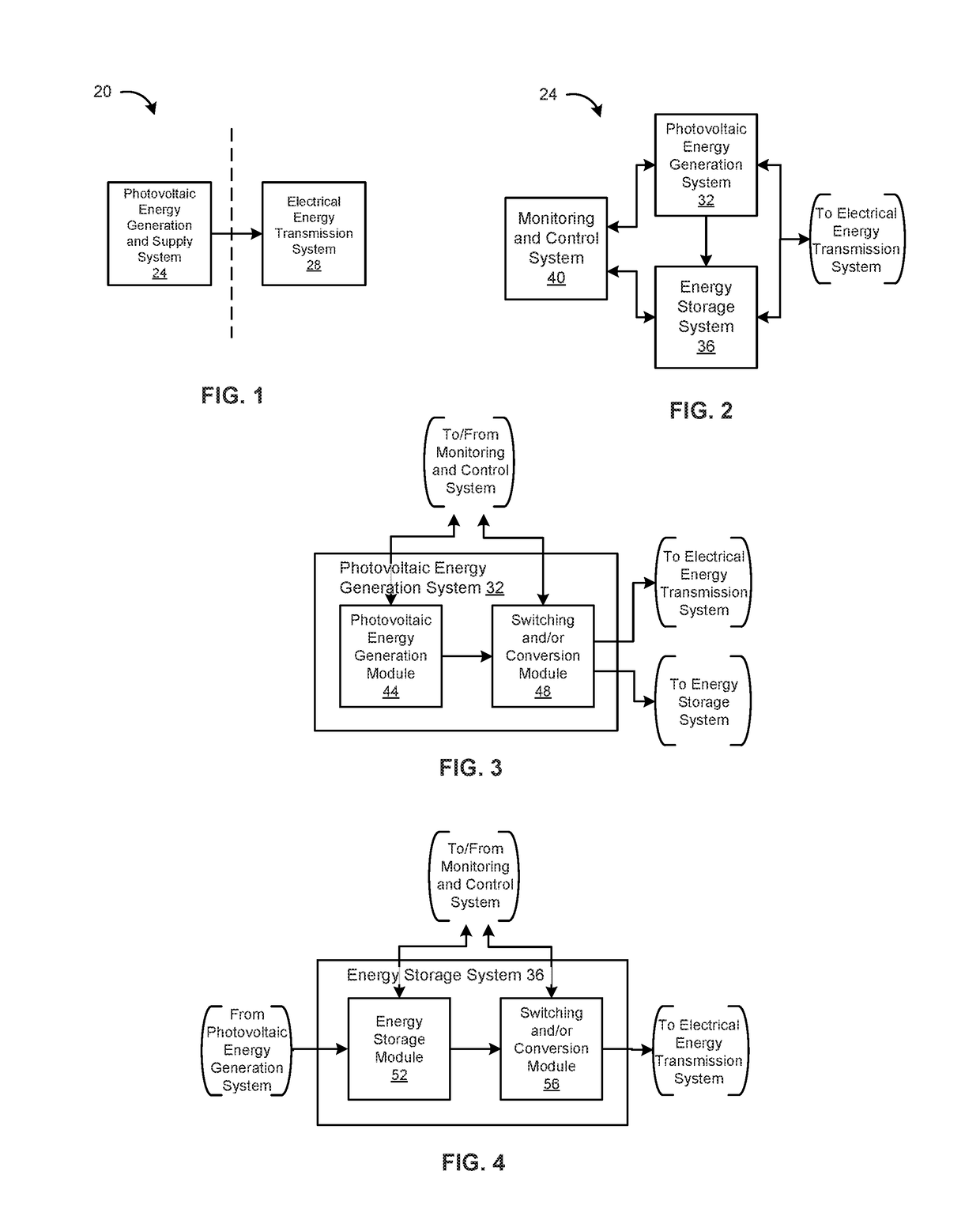
[0025]FIG. 1 depicts an example embodiment of an energy generation and transmission system 20. The illustrated energy generation and transmission system 20 includes a photovoltaic energy generation and supply system 24 and an electrical energy transmission system 28, where the photovoltaic energy generation and supply system 24 generates electrical energy from solar energy, and supplies electrical energy to the electrical energy transmission system 28. The electrical energy transmission system 28 receives electrical energy from the photovoltaic energy generation and supply system 24, and transmits the electrical energy to end users for consumption.

[0026]The photovoltaic energy generation and supply system 24 and the electrical energy transmission system 28 can each be owned, operated and / or located on the premises of different entities, such as corporations, public utilities, governmental bodies, etc. For example, the photovoltaic energy generation and supply system 24 can be owned,...


PUM


Abstract

A method of controlling a photovoltaic system includes: receiving a forecast of energy generation by the photovoltaic system for a predetermined time period; determining a revenue generation objective function characterizing revenue generated by feeding electrical energy from the photovoltaic system into an energy transmission system; determining constraints on the feed-in of electrical energy into the energy transmission system, at least some of the constraints being a function of the forecast; optimizing the revenue generation objective function as constrained to determine energy feed-in and storage actions; and executing the determined energy feed-in and storage actions. The method, for example, utilizes a simplified revenue generation module including a linear revenue generation objective function and a plurality of linear constraints, which can enable optimization using a mixed integer linear programming approach. The method steps can be performed iteratively, at each of a plurality of predetermined time intervals during the predetermined time period.

Description

BACKGROUND INFORMATION[0001]Photovoltaic power plants generate electric energy from solar energy, and feed the generated electric energy to an electric energy transmission system, often to generate revenue. Photovoltaic power plants and electric energy transmission systems are typically operated by different entities, and the electric energy transmission system is likely to place requirements on the form of the electric energy it receives from the photovoltaic power plant. Such requirements originate from limits of the electric energy transmission system's ability to receive electric energy, energy regulations, market considerations, etc., as well as other factors, and power levels required by the electric energy transmission system may differ substantially from power levels naturally generated by the photovoltaic power plant. Failure of the photovoltaic power plant to fulfil these requirements results in a penalty in the form of a reduction in payment from the electric energy trans...

Claims


Application Information

Patent Timeline
IPC IPC(8): G05B19/048H02J3/38H02J3/46H02S10/20
CPCG05B19/048H02S10/20G05B2219/2639H02J3/46H02J3/383H02J3/28H02J3/32Y02E70/30H02J2203/20H02J2300/24H02J3/381Y02E10/56Y02E60/00Y04S40/20
Inventor CHEN, FANGROY, BINAYAKJASIM, AHMED
Owner ROBERT BOSCH GMBH
Why Eureka
Try Eureka