
Brightness control for spatially adaptive tone mapping of high dynamic range (HDR) images

a high dynamic range (hdr) image and tone control technology, applied in image enhancement, image analysis, instruments, etc., can solve the problems of loss of image detail, unable to reproduce such hdr images in a visually acceptable format, and most display devices have much more limited dynamic rang

Inactive Publication Date: 2018-02-15
INTEL CORP
View PDF12 Cites 8 Cited by
  • Summary
  • Abstract
  • Description
  • Claims
  • Application Information

AI Technical Summary

Benefits of technology

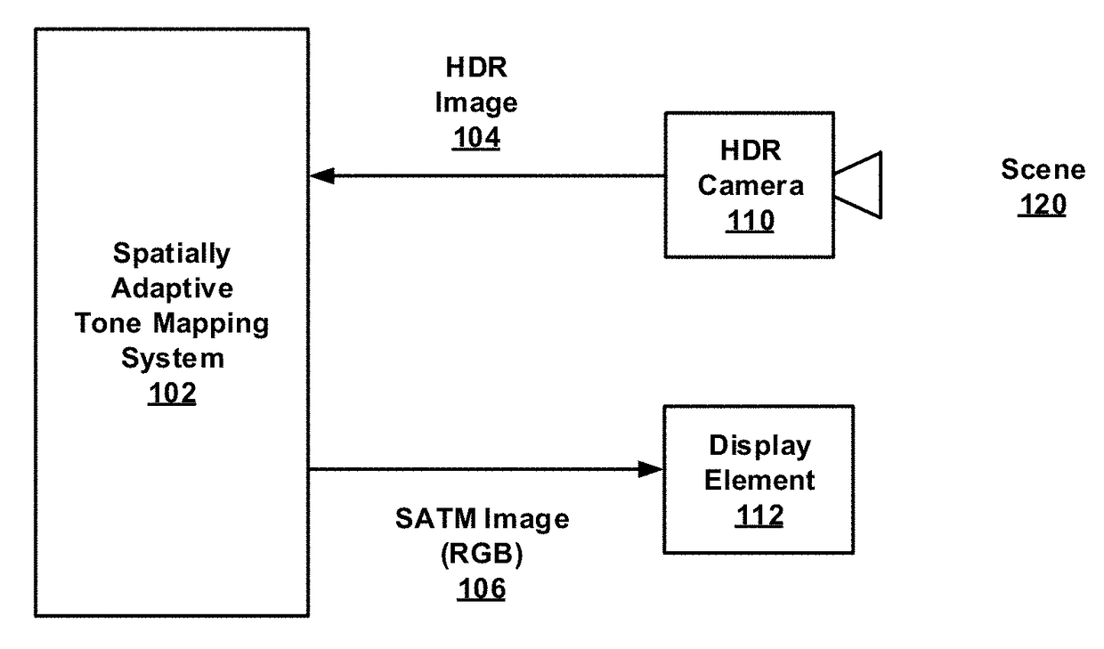
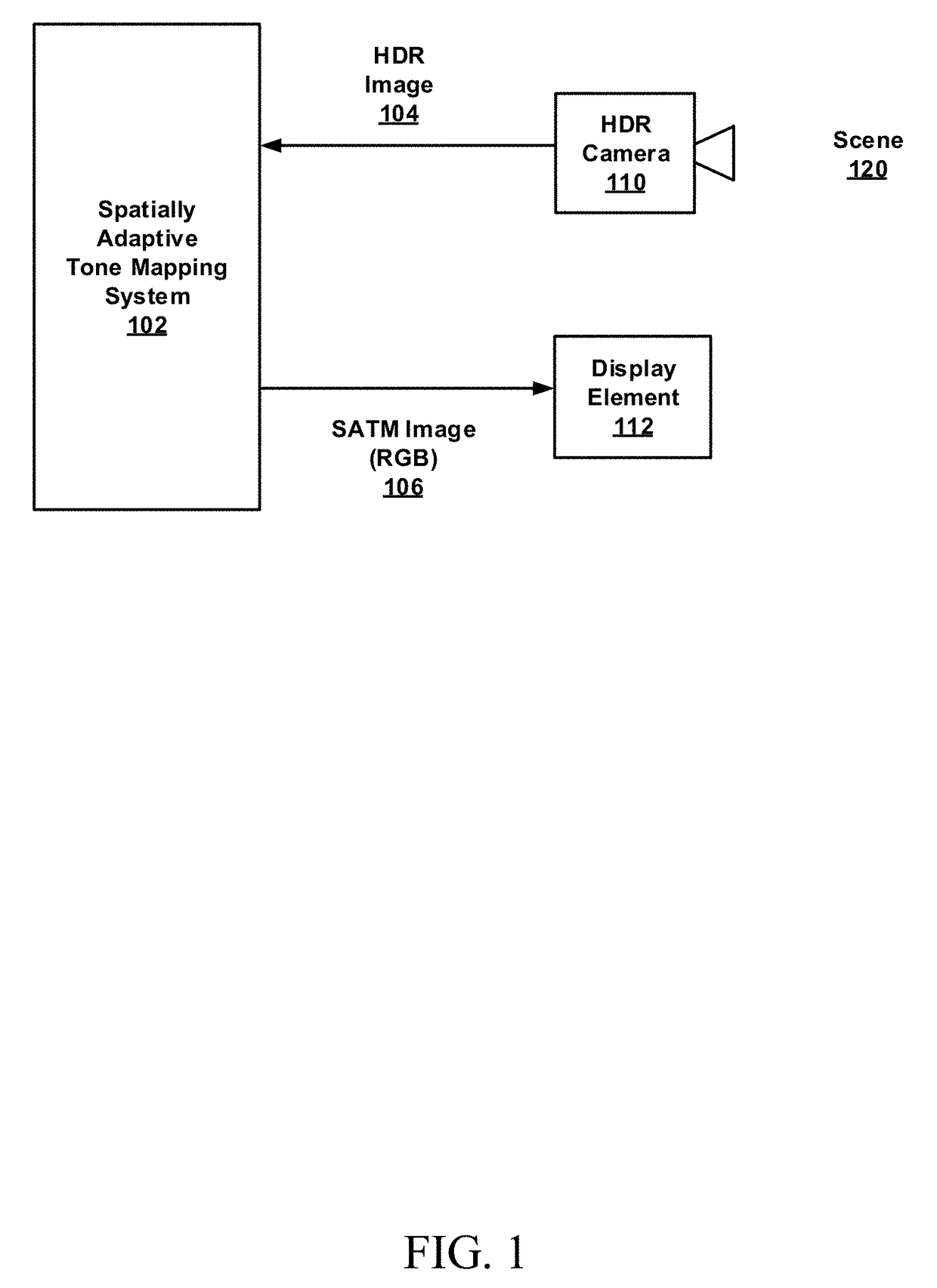
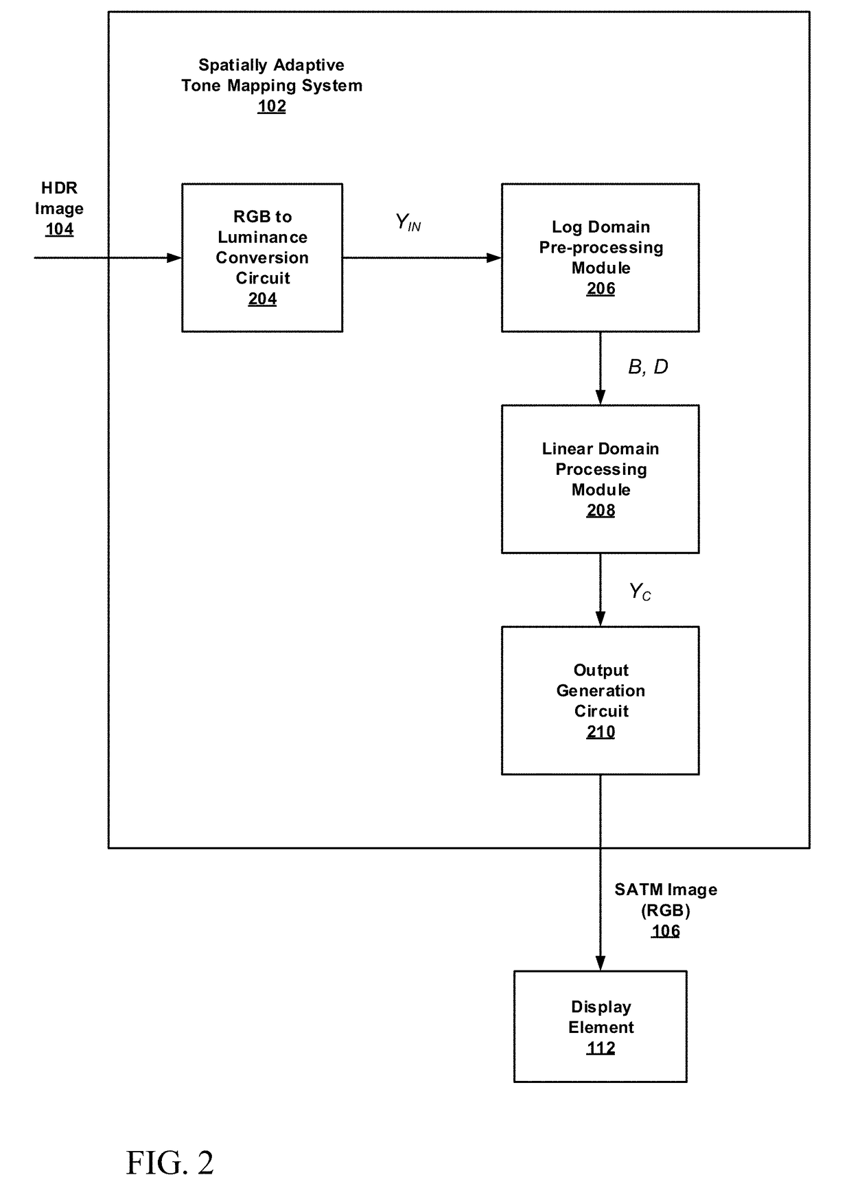
The patent text describes a technique for displaying high dynamic range (HDR) images on devices with lower dynamic range capability. The technique involves spatially adaptive tone mapping (SATM) with dynamic brightness and contrast control. The SATM processing includes dynamic range compression operations that preserve image details in both bright and dark regions of the image. The disclosed techniques include a pre-processing operation and a subsequent dynamic range compression operation, which are performed in the logarithmic and linear domains, respectively. The pre-processing operation decomposes luminance data into multiple layers with varying detail using a guided edge-aware filter to provide relatively more efficient execution. The technical effect of the patent text is the ability to display HDR images on devices with lower dynamic range capability, while maintaining image detail in both bright and dark areas.

Problems solved by technology

Currently, however, most display devices have much more limited dynamic range (e.g., low dynamic range or LDR), and are unable to reproduce such HDR images in a visually acceptable format.
Attempts to display an HDR image on a standard LDR display typically results in regions of the image that are either washed out or blacked out, or both, with a resulting loss of image detail.
Global operators apply the same mapping function to each image pixel and provide global contrast reduction, but typically suffer from loss of detail in the dark and bright areas of the image.
Local operators, on the other hand, are better at preserving local image features such as details in bright and dark areas, but generally suffer from low global contrast and may introduce image artifacts such as halo effects.
Additionally, local tone mapping operators are more computationally intensive and are generally not suitable for real-time applications.

Method used


Image

  • Brightness control for spatially adaptive tone mapping of high dynamic range (HDR) images
  • Brightness control for spatially adaptive tone mapping of high dynamic range (HDR) images
  • Brightness control for spatially adaptive tone mapping of high dynamic range (HDR) images

Examples


example 2

[0085 includes the subject matter of Example 1, further comprising generating compressed luminance data based on a multiplicative product of the compressed linear domain layers.

example 3

[0086 includes the subject matter of Examples 1 or 2, further comprising generating a compressed output image based on scaling of red-green-blue (RGB) data from the received image by a ratio of the compressed luminance data to the luminance data from the received image.

example 4

[0087 includes the subject matter of any of Examples 1-3, wherein the statistics associated with brightness are based on an average of samples of the adjusted log domain base layer.


PUM


Abstract

Techniques are provided for spatially adaptive tone mapping with dynamic brightness control. A methodology implementing the techniques according to an embodiment includes converting luminance data, from a received HDR image, to a logarithm domain and decomposing the converted data into a base layer, and one or more detail layers. The method also includes adjusting the layers, through shifting and scaling of the base layer and scaling of the detail layers, to map the amplitude data into a selected range. The method further includes converting the adjusted layers from the logarithm domain to a linear domain and calculating a tone compression parameter based on statistics of the adjusted log domain base layer. The statistics are associated with brightness of the received image. The method further includes applying a global tone compression function, based on the tone compression parameter, to the converted linear domain base layer to generate compressed linear domain layers.

Description

BACKGROUND[0001]Cameras, and other imaging devices, with the capability to provide increasingly high dynamic range images, are becoming more widely available. Such HDR images are able to capture a wider range of luminosity or brightness than is possible with more traditional imaging devices and techniques. This can be useful when the subject matter of the photograph contains both extremely bright and extremely dark regions, such as, for example, a mixture of sunlit areas and shadowed areas. HDR imaging is sometimes accomplished by capturing multiple images of the same scene, each taken at narrow but varying exposure levels, and combining them into a composite image. HDR images may also be obtained with sensors that have greater dynamic range, and which can generate pixel values with an increased number of bits to represent that entire range, without losing detail through truncation of least significant bits. Currently, however, most display devices have much more limited dynamic ran...

Claims


Application Information

Patent Timeline
Patent Type & Authority Applications(United States)
IPC IPC(8): G06T5/00G09G3/20G06T3/40
CPCG06T5/007G06T3/40G09G2300/0465G06T2207/20208G09G3/2007G06T5/90
Inventor EL MEZENI, DRAGOMIR
Owner INTEL CORP
Learn More