
High dynamic range color conversion correction

a color conversion correction and high dynamic range technology, applied in the field of audiovisual processing, can solve the problem that the complexity of the disclosed techniques is significantly lower than that of the conventional approaches, and achieve the effect of significantly lower complexity of the disclosed techniques

Active Publication Date: 2018-02-15
NETFLIX
View PDF0 Cites 5 Cited by
  • Summary
  • Abstract
  • Description
  • Claims
  • Application Information

AI Technical Summary

Benefits of technology

The disclosed techniques allow for more accurate HDR images to be generated relative to conventional methods, while at the same time reducing the complexity of the process. This means that optimal component values can be determined in real-time with fewer iteration cycles. The type of filter used during pre-processing of the HDR images can also be signaled to a receiving device, resulting in more accurate images relative to the original HDR images.

Problems solved by technology

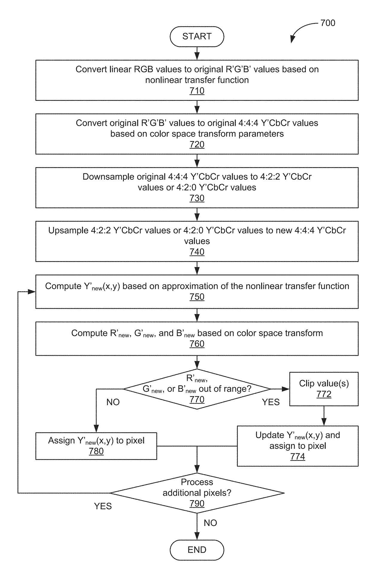
Additionally, the complexity of the disclosed techniques is significantly lower than that of the conventional approaches, enabling an optimal component value (e.g., a luma value) to be determined in real-time via fewer iterations (e.g., one or two iterations) than in conventional approaches.

Method used


Image

  • High dynamic range color conversion correction
  • High dynamic range color conversion correction
  • High dynamic range color conversion correction

Examples


example 1

t Function

[0037]In some embodiments, the distance (D) between RGBnew(x,y) and RGBorg(x, y) could be measured as the Euclidean norm (e.g., the squared error for each component):

D=(Rnew(x,y)−Rorg(x,y))2+(Gnew(x,y)−Gorg(x,y))2+(Bnew(x,y)−Borg(x,y))2  (3)

[0038]Omitting sample coordinates for simpler notation, the cost function is as follows:

D=(Rnew−Rorg)2+(Gnew−Gorg)2+(Bnew−Borg)2  (4)

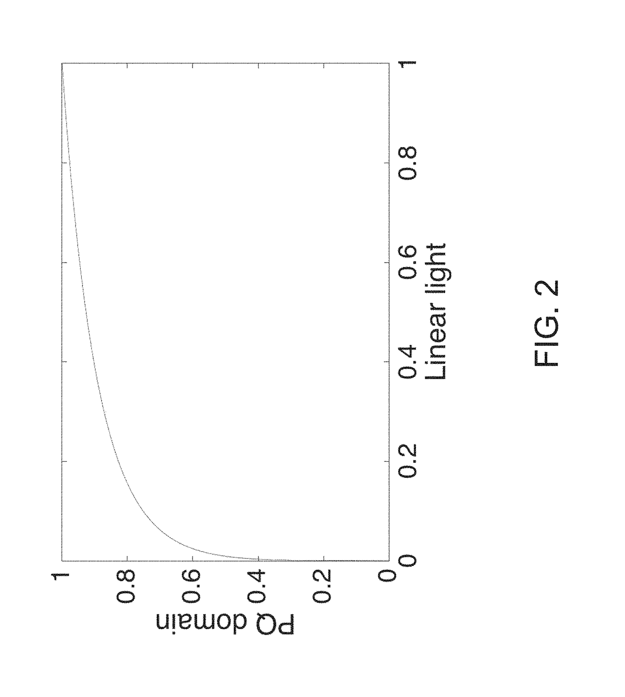
[0039]In a more general case, we can also weight the importance of each color component R, G and B with a weighting factor wX, where X corresponds to a color component, wR, wG, and wB. Then, our cost function would take a form of Equation 5 or Equation 6, where f is the EOTF function, such as the ST.2084 EOTF PQ.:

D=wR(Rnew−Rorg)2+wG(Gnew−Gorg)2+wB(Bnew−Borg)2  (5)

D=wR(f(R′new)−f(R′org)2+wG(f(G′new)−f(G′org))2+wB(f(B′new)−f(B′org)2  (6)

[0040]The values R′, G′ and B′ can be obtained from the original Y′CbCr values by applying an inverse color transform, which depends on the color space associated with the Y′...

example 2

st Function

[0064]In some embodiments, the distance (D) could be measured as a sum of weighted differences between individual R, G, and B components of RGBnew(x,y) and RGBorg(x, y). In such embodiments, the difference between the two values could be calculated according to Equation 20, where wR, wG, and wB are the weights corresponding to each color component and R, G, and B.

D=wR(Rnew(x,y)−Rorg(x,y))+wG(Gnew(x,y)−Gorg(x,y))+wB(Bnew(x,y)−Borg(x,y))  (20)

[0065]Then, after omitting pixel coordinates for a simpler notation, the cost function is defined by Equation 21 or Equation 22, where f(X) is the EOTF function:

D=wR(Rnew−Rorg)+wG(Gnew−Gorg)+wB(Bnew−Borg)  (21)

D=wR(f(R′new)−f(R′org))+wG(f(G′new)−f(G′org))+wB(f(B′new)−f(Borg))  (22)

[0066]As noted above, the transfer function domain values R′, G′, and B′ can then be obtained from Y′CbCr by applying an inverse color transform, such as the BT.709 and BT.2020 transform:

(R′G′B′)=(a1,1a1,2a1,3a2,1a2,2a2,3a3,1a3,2a3,3)(Y′CbCr)(23)

[0067]In vari...


PUM


Abstract

One embodiment of the present invention sets forth a technique for correcting color values. The technique includes downsampling first color space values to generate downsampled color space values and upsampling the downsampled color space values via a first upsampling filter type to generate second color space values. The technique further includes modifying at least one component value included in the downsampled color space values based on a first component value included in the first color space values, a second component value included in the second color space values, and an approximation of a nonlinear transfer function. The technique further includes at least one of (i) storing an indication of the first upsampling filter type in conjunction with a video bitstream associated with the at least one component value, and (ii) transmitting the indication of the first upsampling filter type to a receiving device in conjunction with the video bitstream.

Description

CROSS-REFERENCE TO RELATED APPLICATIONS[0001]This application is a continuation-in-part of co-pending U.S. patent application titled, “HIGH DYNAMIC RANGE COLOR CONVERSION CORRECTION,” filed on Jun. 10, 2016 and having Ser. No. 15 / 179,857, which claims the priority benefit of the U.S. Provisional Patent Application titled, “APPROACH FOR HIGH DYNAMIC RANGE COLOR CONVERSION,” filed on Nov. 9, 2015 and having Ser. No. 62 / 253,098, and the U.S. Provisional Patent Application titled, “APPROACH FOR HIGH DYNAMIC RANGE COLOR CONVERSION,” filed on Nov. 16, 2015 and having Ser. No. 62 / 256,080. This application also claims the priority benefit of the U.S. Provisional Patent Application titled, “HIGH DYNAMIC RANGE COLOR CONVERSION TECHNIQUES,” filed on Oct. 5, 2016 and having Ser. No. 62 / 404,720. The subject matter of these related applications is hereby incorporated herein by reference.BACKGROUND OF THE INVENTIONField of the Invention[0002]Embodiments of the present invention relate generally to...

Claims


Application Information

Patent Timeline
Patent Type & Authority Applications(United States)
IPC IPC(8): H04N19/132H04N19/85H04N9/64H04N19/186
CPCH04N19/132H04N19/186H04N19/85H04N9/646G06T2207/20208H04N5/20H04N1/60
Inventor NORKIN, ANDREY
Owner NETFLIX
Learn More