Making 3D printed shapes with interconnects and embedded components

a 3d printed, interconnecting technology, applied in the direction of additive manufacturing processes, printed circuit non-printed electric components association, manufacturing tools, etc., can solve the problems of limiting printing freedom, hindering printing process and speed, and limiting the printing freedom, so as to achieve better thermal transfer, increase thermal conductivity of functional materials, and improve thermal conductivity

Inactive Publication Date: 2018-02-22
SIGNIFY HLDG BV
View PDF4 Cites 26 Cited by
  • Summary
  • Abstract
  • Description
  • Claims
  • Application Information

AI Technical Summary

Benefits of technology

[0039]The functional material may also be used for thermal management. Hence, the functional material may have thermally conductive properties. Especially, the thermal conductivity of such functional material is thus higher than the thermal conductivity of surrounding 3D printed material, such as at least 5 times higher. Especially, the thermally conductive material has a thermal conductivity of at least 0.5 W / (m·K), such as at least 0.5 W / (m·K). Especially, the (surrounding) printed material has a thermal conductivity of at least 5 times lower, such as at maximum 0.1 W / (m·K). Thermal management may be relevant in 3D printed objects with functional components that heat up. Electrical interfaces like PCB circuits are often combining electrical and thermal functions. Very often, the metallic region close to the component is extended to allow thermal spreading. Also, metal is added under and around the component for more thermal spreading, better thermal transfer to the next thermal interface or even direct heat sinking. All of these aspects require special treatments and added costs. Also because of their typical 2D nature layers will be added to the system increasing real estate around the component. One does not really control their 3D shape. By injecting thermal structures close and around the components, one can make morphological design giving the best 3D compromise of the desired shape with regard to the thermal management needed and also other aspects of integration, like with regard to size / shape of the product. Thermal(ly conductive) channels could also be used to transfer the heat through complex structures from the component to a heat sink, allowing having them far away from each other and even not aligned. Intermediate spreading structures can also allow to couple or decouple components far away or close to each other. An example of this problem can be found in multi-color LED devices. LEDs of different colors generate different amounts of heat and have different temperature sensitivities. One could precisely balance / compensate for these differences and imperfections.

Problems solved by technology

Fitting wires in 3D-printed parts requires complex printing geometries and limits the printing freedom.
In addition, applying wires during the printing severely hinders the printing process and speed (e.g. the printing has to be paused to inserts wires).
Also the threading connections may remain a weak point.
Printing pure metal conductive paths in a part is not possible with the current 3D-printing technologies.
Further, techniques that allow printing metal (laser or e-beam induced metal particle sintering / melting) do not allow the concomitant printing of another material.
Techniques that allow multi-material printing like Fused Deposition Modelling (FDM) or jetting, etc., do not yet allow the printing of electrically conductive metals.
This exposes components to mechanical damage and can make circuits more fragile and prone to damage.
It does also leave tracks and component pads exposed, resulting in potential health risks for user (e.g. electrocution) and reliability risks for the product (e.g. moisture induced short circuits and corrosion).
The disadvantage of this approach is that FDM compatible conducting materials are not widely available and are in general also not highly electrically and thermally conductive (certainly compared to metal wires).
This means that 3D printed conductive tracks that are used to connect components will have relatively large resistances and cannot be used to conduct large currents.
Using these materials in circuits will result in large losses, thermal heating and low efficiencies.

Method used


Image

  • Making 3D printed shapes with interconnects and embedded components
  • Making 3D printed shapes with interconnects and embedded components
  • Making 3D printed shapes with interconnects and embedded components

Examples


Embodiment Construction

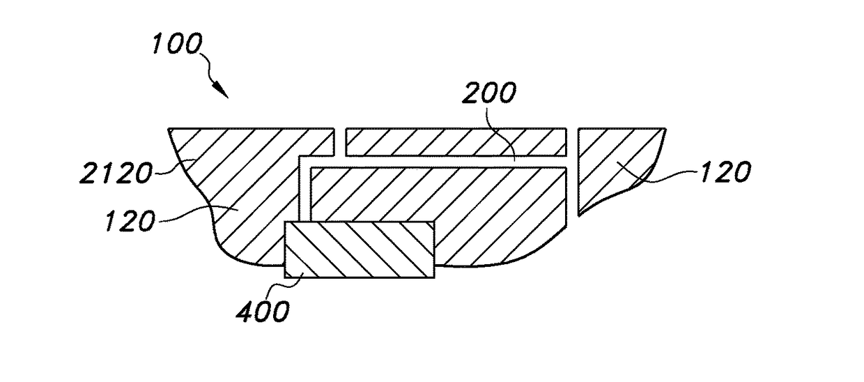
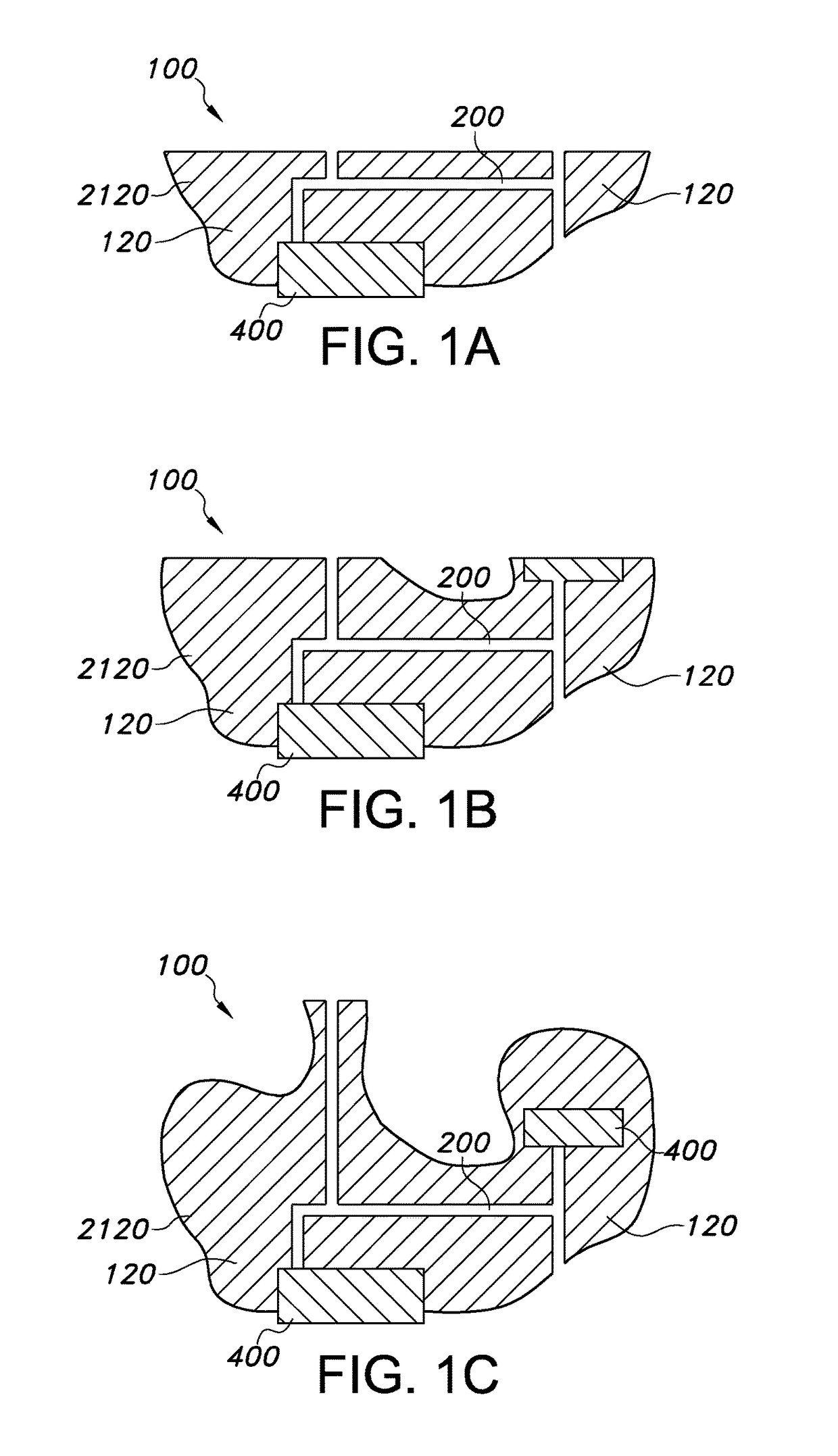
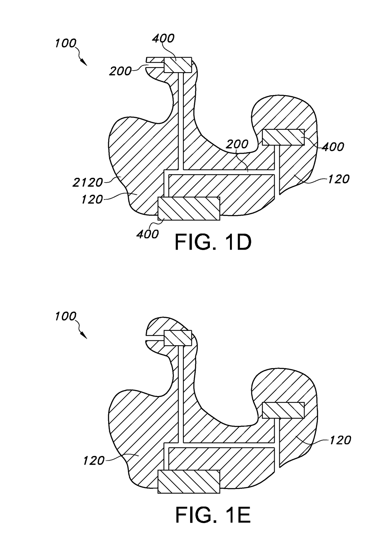
[0050]In FIGS. 1a-1i an example is schematically shown with functional components at the bottom of the 3D printed part (or 3D printed object 100) as well as embedded inside the 3D printed part. In this example we show a 3DP part with three electrical components. The process is not limited to this example of three electrical components and multiple electrical components could be added in the same way. In FIG. 1a a process step or stage is shown, wherein an electrical component 400 is first placed on the build platform and overprinted with a few layers (indicated with printed material 120). The printing of the part is started, leaving gaps where the tunnels (or channels) will be formed. Reference 2120 indicates printed material being electrically insulating. In a next stage, see FIG. 1b, a second electrical component is added. The second electrical component may be aligned such that the conductive pads are over the desired tunnels running upwards from conductive pads on the first elec...


PUM

PropertyMeasurementUnit
viscosityaaaaaaaaaa
temperatureaaaaaaaaaa
sizeaaaaaaaaaa

Abstract

Method and apparatus for the production of a 3D printed object (100), wherein the method comprises (i) a 3D printing stage, the 3D printing stage comprising 3D printing a 3D printable material (110) to provide the 3D printed object (100), wherein the 3D printing stage further comprises forming during 3D printing a channel (200) in the 3D printed object (100) under construction, wherein the method further comprises (ii) a filling stage comprising filling the channel (200) with a flowable material (140), wherein the flowable material (140) comprises a functional material (140a), wherein the functional material (140a) has one or more of electrically conductive properties, thermally conductive properties, light transmissive properties, and magnetic properties, and immobilizing said functional material (140a).

Description

FIELD OF THE INVENTION[0001]The invention relates to a method for the production of a 3D printed object, especially including a functional component. The invention also relates to such object per se, for instance obtainable with such method. The invention further relates to a 3D printer, which may for instance be used in such method for the production of a 3D printed object, especially including a functional component.BACKGROUND OF THE INVENTION[0002]Additive technologies wherein a material is incorporated in an object made via such technology are known in the art. US2013303002, for instance, describes a three-dimensional interconnect structure for micro-electronic devices and a method for producing such an interconnect structure. The method comprises a step wherein a backbone structure is manufactured using an additive layer-wise manufacturing process. The backbone structure comprises a three-dimensional cladding skeleton and a support structure. The cladding skeleton comprises lay...

Claims


Application Information

Patent Timeline
Patent Type & Authority Applications(United States)
IPC IPC(8): B29C64/106B29C70/70B29C70/72
CPCB29C64/106B29C70/70B29C70/72B33Y10/00B33Y30/00B33Y80/00H05K1/18H05K3/12B29C64/118
Inventor TALGORN, ELISE CLAUDE VALENTINELIBON, SEBASTIEN PAUL RENEVAN DEN ENDE, DAAN ANTONJACOBS, EGBERTUS REINIERBEAUMONT, DAVECHERENACK, KUNIGUNDE HADELINDEHIKMET, RIFAT ATA MUSTAFA
Owner SIGNIFY HLDG BV
Why Eureka
Try Eureka