Heat transfer system

a technology of heat transfer system and water heater, which is applied in the field of energy conservation, can solve the problems of high energy cost to maintain the hot water temperature, inefficient heat transfer of water in storage tanks, and scalding of humans with high temperature 140° f. storage tank water, etc., and achieves the effect of increasing the surface area of the microchannel, increasing the surface area of the exterior surface, and increasing the thermal transfer

Active Publication Date: 2012-06-21
GRUNDFOS HLDG
View PDF9 Cites 53 Cited by
  • Summary
  • Abstract
  • Description
  • Claims
  • Application Information

AI Technical Summary

Benefits of technology

[0017]Optionally, the exterior surface of the outer sleeve may have enhancements to increase a surface area of the exterior surface for greater thermal transfer between the outer sleeve and the first fluid. The exterior surface may have interstices extending into a flow path of the first fluid. The microchannels may have enhancements to increase the surface area of the microchannels for greater thermal transfer between the microchannel unit and the second fluid. The microchannels may have interstices extending into a flow path of the second fluid. Optionally, the first fluid may be potable water and the second fluid may be a refrigerant. The microchannel unit and the outer sleeve may extend longitudinally between ends with the grooves extending between corresponding ends and being in fluid communication with a breach manifold at least one of the ends.

Problems solved by technology

This can be a problem during peak usage hours, e.g., mornings when patients are generally taking warm showers or evenings when onsite laundries need hot water.
Energy costs may be high to maintain the hot water temperature.
Another dilemma facing building engineers is the scalding of humans with the high temperature 140° F. storage tank water.
It is inefficient to heat water in storage tanks to 140° F. to prevent Legionella only to dilute to 120° F. at the point of service.
With or without storage, emissions from the fossil fuel boilers or water heaters are known to cause increased pollution and global warming.
Moreover, as fossil fuel becomes scarcer, the price of heating hot water will undoubtedly escalate.
This custom engineered isolation loop is both costly and inefficient.
This approach has some disadvantages in that the heat exchangers are not cleanable or serviceable.
Moreover the vented chamber between the two requires a great deal of costly heat transfer surface.
Moreover these heat exchangers are vastly inefficient compared to single wall heat exchangers.
Often the conventional heat pump water heating systems have vapor compression systems that are not dynamic enough to satisfy the demands of an instantaneous heating to 120° F. and therefore are applied with storage tanks maintaining approximately 140° F.
However, ammonia cannot be applied to commercially available double wall BPHE's because there is copper in the system which is attacked by the refrigerant.
These refrigerants however are flammable in concentrations between approximately 2% to 9% of concentration and fail safe containment heat exchanger systems are not commercially available.
Another problem associated with known heat transfer systems, is that commercially available water to refrigerant evaporators are susceptible to freezing, particularly when the recovery temperature is below 48° F. or the system is operating in a low flow situation.
The normal failure mode is ice forming on the water side of the refrigerant evaporators and the fragile wall breaches to the refrigerant side often destroying the compressor.
This however shuts off the production of hot water and compromises reliability.
However, the prior art fails to address building systems in cooler climates without an air conditioning load or even buildings in warm climates that do not have the availability to recover from a chilled water or condenser water system.

Method used


Image

  • Heat transfer system
  • Heat transfer system
  • Heat transfer system

Examples


Embodiment Construction

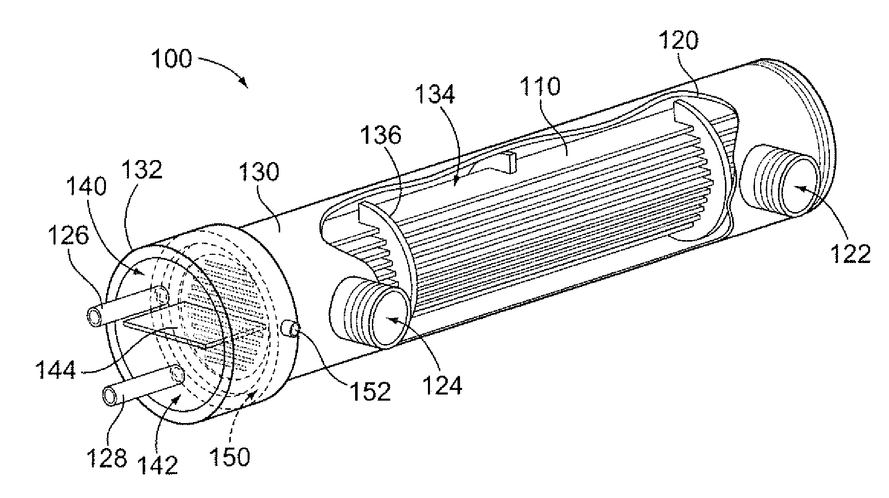
[0029]FIG. 1 illustrates a heat exchanger 100 formed in accordance with an exemplary embodiment. The heat exchanger may be used as part of a heat transfer system 102 (shown in FIG. 6), such as a vapor compression system. Those skilled in the art of vapor compression systems know that the refrigerant in the heat transfer system 102 goes through four phases. The desuperheater is single phase gas heat transfer. The condenser is a bi-phase heat transfer from a gas to a liquid. The sub-cooler is a single phase liquid heat transfer. Finally the evaporator is a bi-phase going from a liquid to a gas heat transfer. In an exemplary embodiment, heat exchangers, such as the heat exchanger 100, are used at each of the phases. The heat exchangers 100 may be altered to take advantage of the particular phase of the refrigerant, but generally include similar features.

[0030]The heat exchanger 100 includes a plurality of heat transfer devices 110 held within a housing 120. In an exemplary embodiment, ...


PUM

PropertyMeasurementUnit
temperatureaaaaaaaaaa
GWPaaaaaaaaaa

Abstract

A heat transfer system includes a heat exchanger configured to transfer heat between a first fluid and a second fluid. The heat exchanger includes an outer sleeve and a microchannel unit. The outer sleeve has an interior surface defining a cavity and an exterior surface configured to be in direct thermal communication with the first fluid. The microchannel unit is received in the cavity. The microchannel unit has a plurality of microchannels configured to receive the second fluid therein and be in direct thermal communication with the second fluid. The microchannel unit has an exterior surface in direct thermal communication with the interior surface of the outer sleeve to transfer heat therebetween. At least one of the interior surface of the outer sleeve and the exterior surface of the microchannel unit has grooves defining breach channels for the first fluid or the second fluid should a breach in the outer sleeve or the microchannel unit occur.

Description

CROSS REFERENCE TO RELATED APPLICATIONS[0001]This application claims the benefit of U.S. Provisional Application No. 61 / 423,577 filed Dec. 15, 2010, the subject matter of which is herein incorporated by reference in its entirety.BACKGROUND OF THE INVENTION[0002]The subject matter herein relates generally to the field of energy conservation, and, more particularly, to the field and related methods of heat transfer systems for warming water.[0003]Buildings, such as hospitals, for example, may need to provide large quantities of hot water on demand to patients or processes. This can be a problem during peak usage hours, e.g., mornings when patients are generally taking warm showers or evenings when onsite laundries need hot water. Many hospitals use hot water storage tanks to store hot water so that patients and laundries may use hot water on demand without compromising the temperature. Water stored in hot water storage tanks are generally heated using fuel based heaters. Hot water tem...

Claims


Application Information

Patent Timeline
Patent Type & Authority Applications(United States)
IPC IPC(8): F25B27/00F28D15/00F25B49/02
CPCF28F9/0219F28F19/006F28F19/02F28D7/1684F28F1/003F24D17/02F28F2260/02F24D2200/20F24D2200/31F24D17/0005F28F1/022Y02B30/18
Inventor JAGUSZTYN, TADEUSZ FRANK
Owner GRUNDFOS HLDG
Why Eureka
Try Eureka