Time Delay Toll System for Charging Piles and Its Method

a toll system and charging pile technology, applied in the field of new energy vehicles, can solve the problems of wasting charging parking spaces, charging piles that are often faced by charging piles, and hindering the use of other customers, so as to improve the availability factor of charging piles and parking stalls, and increase the efficiency of charging piles

Active Publication Date: 2018-02-22
BEIJING X CHARGE TECH CO LTD
View PDF3 Cites 3 Cited by
  • Summary
  • Abstract
  • Description
  • Claims
  • Application Information

AI Technical Summary

Benefits of technology

[0004]For the above technical problem, the present invention provides a time delay toll system for charging piles, which can promote the electric automobile user to leave as early as possible or settle accounts as early as possible after his charging is end, and can improve the availability factor of charging piles and parking stalls, and can increase the efficiency of operation of charging piles.
[0024]By the judgment for the connection status of hardware and flexible toll mechanism, through the economic lever means, the present invention can promote the electric vehicle users to leave as soon as possible after their charging is end, make the charging piles and the parking spaces to the next users, improve the efficiency of the use of parking and charging piles, and increase the operation efficiency of charging piles.

Problems solved by technology

However, the current charging piles are often faced with such a problem: the user is still occupied for a long time and do not leave after charging is end.
This condition greatly hindered the use of the other customers, and resulted in a waste of charging parking spaces and charging piles.

Method used


Image

  • Time Delay Toll System for Charging Piles and Its Method
  • Time Delay Toll System for Charging Piles and Its Method
  • Time Delay Toll System for Charging Piles and Its Method

Examples


Embodiment Construction

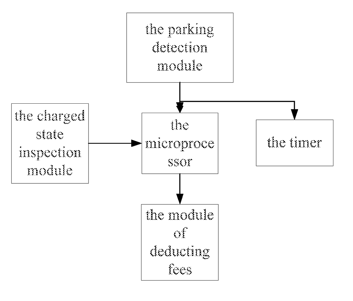
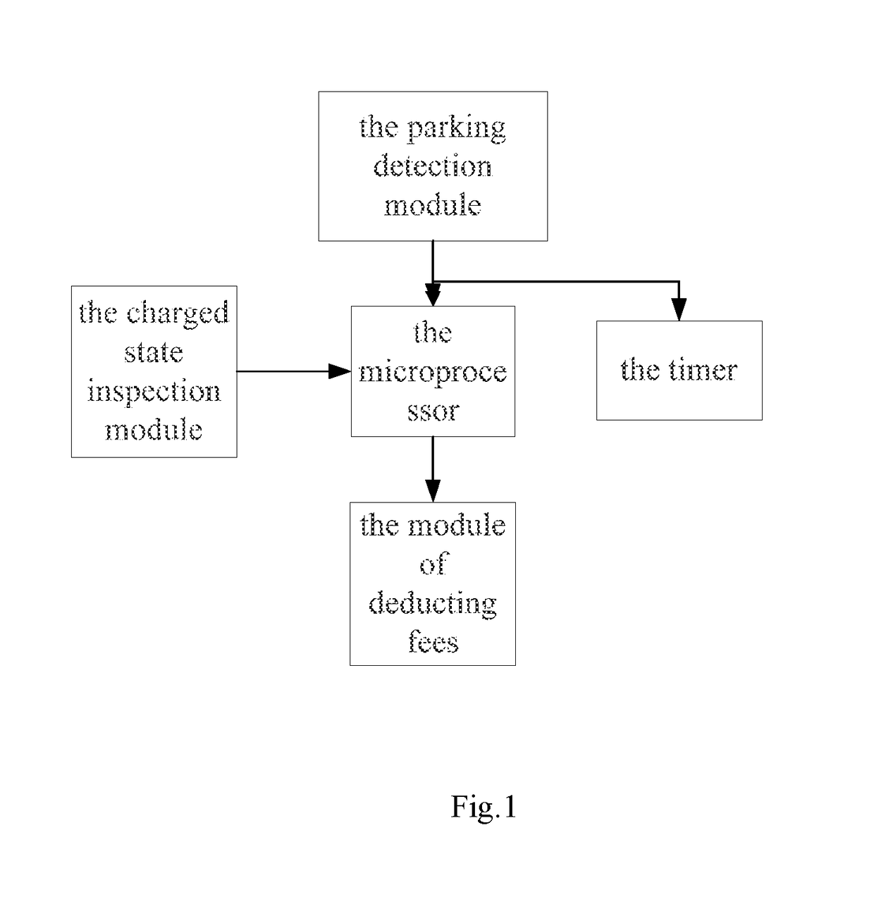
[0027]As shown as FIG. 1, this time delay toll system for charging piles, the system includes:

[0028]the charging state inspection module, which is configured to detect the magnitude of voltage of the communication cables of the charging piles, and send the magnitude of voltage to the microprocessor;

[0029]the parking detection module, which is installed on the parking stall, and is configured to detect whether has an automobile on this parking stall;

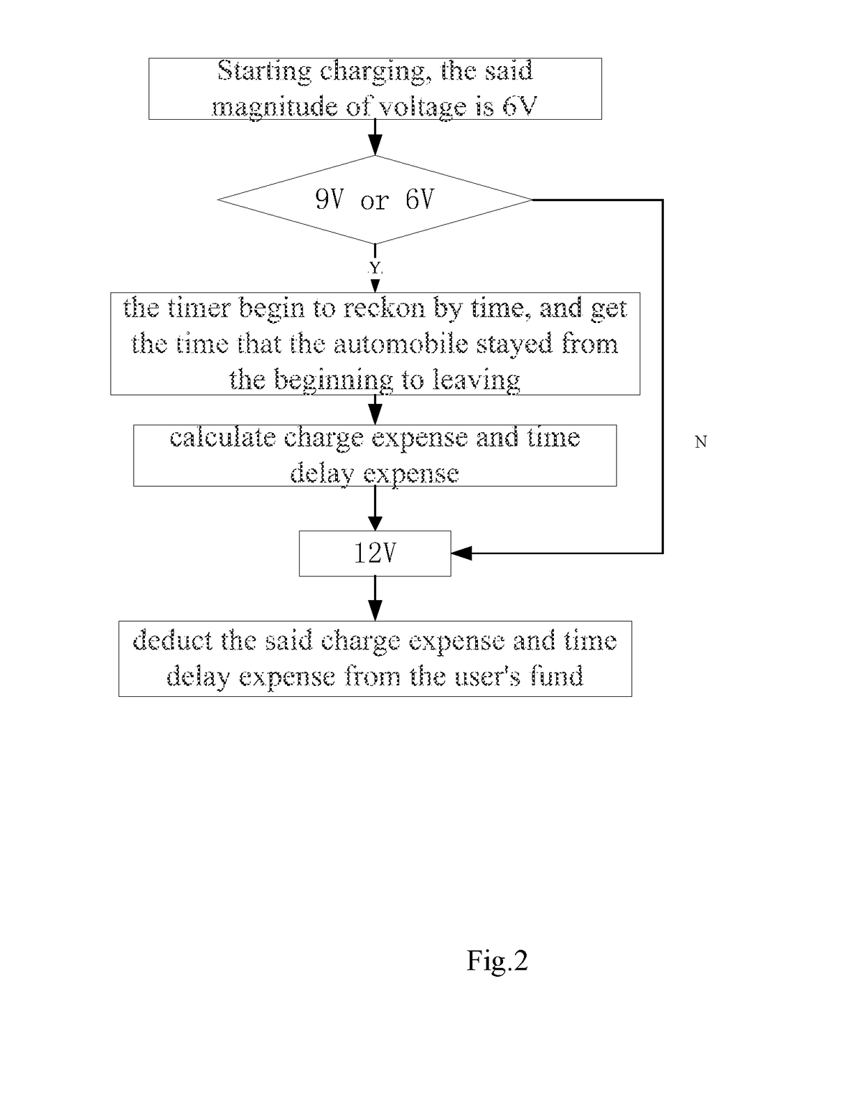
[0030]the microprocessor, which is configured to determine whether the charging is end according to the magnitude of voltage, if yes, then notify the tinier to reckon by time, and send the module of deducting fees the time that the automobile stayed from the beginning to leaving;

[0031]the module of deducting fees, which is configured to calculate charge expense and time delay expense, and is configured to deduct the said charge expense and time delay expense from the user's fund.

[0032]By the judgment for the connection status of hardware ...


PUM


Abstract

The invention discloses a time delay toll system for charging piles, which can promote the electric automobile user to leave as early as possible or settle accounts as early as possible after the charging is end, improve the availability factor of the charging piles and parking stalls, and increase an efficiency of operation of the charging piles. The system includes: the charging state inspection module, which is configured to detect the magnitude of voltage of the communication cables of the charging piles, and send the magnitude of voltage to the microprocessor; the parking detection module, which is installed on the parking stall, and is configured to detect whether has an automobile on this parking stall; the microprocessor, which is configured to determine whether the charging is end according to the magnitude of voltage, if yes, then notify the timer to reckon by time, and send the module of deducting fees the time that the automobile stayed from the time beginning to the car's leaving; the module of deducting fees, which is configured to calculate the charge expense and time delay expense, and is configured to deduct the said charge expense and time delay expense from the user's fund. The method that adopts this time delay toll system for charging piles is also provided.

Description

FIELD OF THE INVENTION[0001]The present invention relates to a technical field of new energy vehicles, and particularly relates to a time delay toll system for charging piles, and a method that adopts this system.BACKGROUND OF THE INVENTION[0002]With the development of the technology and the science, due to the energy saving and environmental protection of the new energy vehicles, new energy vehicles are more and more popular in common people. Therefore, in the current parking lot, more and more charging piles are used.[0003]However, the current charging piles are often faced with such a problem: the user is still occupied for a long time and do not leave after charging is end. This condition greatly hindered the use of the other customers, and resulted in a waste of charging parking spaces and charging piles.SUMMARY OF THE INVENTION[0004]For the above technical problem, the present invention provides a time delay toll system for charging piles, which can promote the electric automo...

Claims


Application Information

Patent Timeline
Patent Type & Authority Applications(United States)
IPC IPC(8): B60L11/18G01R31/02G07B15/02
CPCB60L11/185G07B15/02G01R31/021B60L2240/80B60L2250/12Y02T90/16Y02T10/7072Y02T90/14Y04S30/14B60L53/64B60L53/11Y02T10/70Y02T90/12Y02T90/167G01R31/58H02J7/00032H02J2310/48
Inventor DING, RUI
Owner BEIJING X CHARGE TECH CO LTD
Why Eureka
Try Eureka