Packet tracking

Inactive Publication Date: 2018-02-22
INFERSIGHT LLC
View PDF1 Cites 8 Cited by
  • Summary
  • Abstract
  • Description
  • Claims
  • Application Information

AI Technical Summary

Benefits of technology

[0014]Moreover, a packet's path from source to destination in a network can be traced, and information representing that path can be stored. So that, if, for example, a malicious or otherwise harmfu

Problems solved by technology

However, if the packet fails the validity check, the network may discard the packet or otherwise handle t

Method used


Image

  • Packet tracking
  • Packet tracking
  • Packet tracking

Examples


Embodiment Construction

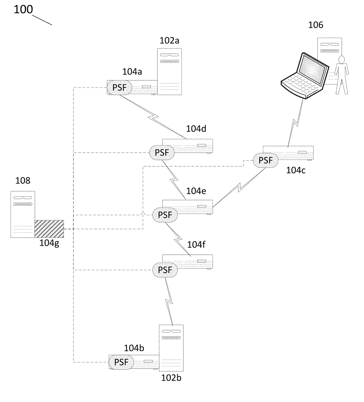
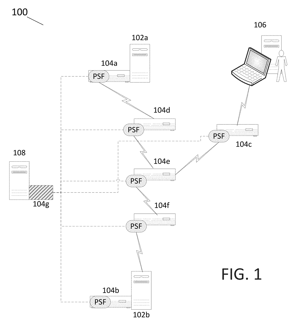
[0023]FIG. 1 is a schematic representation of an exemplary computer network 100 that includes a plurality of network components that are able to communicate with each other over a plurality of network communication links.

[0024]The components in the illustrated network 100 include a first network host 102a, a second network host 102b, a user access terminal 106, and a key manager 108. The components 102a, 102b, and 106 communicate with one another, via packet switching, over the intervening network communication links. To facilitate network communications, the first and second network hosts 102a, 102b have network interface controller (NIC) switches 104a, 104b, which are integral computer hardware components that connect the hosts into the computer network 100. The user access terminal 106 is connected to a network access switch 104c, which is a physically separate hardware component that connects the user access terminal 106 into the computer network 100. There are also three other ...


PUM


Abstract

A computer-based method includes transmitting a packet from a source across a packet-switched network that includes multiple network switches, and attaching, or otherwise associating, a unique signature to the packet at one or more of the network switches. Each unique signature identifies a corresponding one of the network switches, through which the packet passes as it travels from the source toward a destination. The packet and an attached, or otherwise associated, string of signatures from the plurality of network switches, is received at or near the destination in the packet-switched network. In a typical implementation, the validity of the packet is checked, by a validator (e.g., at or near the destination).

Description

CROSS-REFERENCE TO RELATED APPLICATION(S)[0001]This application claims priority to U.S. provisional patent application Ser. No. 62 / 375,948, entitled Packet Tracing—Full Path Disclosure, which was filed on Aug. 17, 2016. The subject matter of the prior application is being incorporated herein by reference in its entirety.FIELD OF THE INVENTION[0002]This disclosure relates to packet tracing and, more particularly, relates to packet tracing from a source to a destination in a computer-based network.BACKGROUND[0003]Source path validation in packet networks may rely on a destination trusting the contents of the frames and packets received which are susceptible to modification by any entity with access to the traffic in a prior segment. As a result, digital security response personnel and systems must review traffic logs consisting of hundreds of millions records with varying levels of detail to determine actual origin and validity.[0004]The disproportionate computational and analytical b...

Claims


Application Information

Patent Timeline
IPC IPC(8): H04L29/06
CPCH04L63/0245H04L63/145H04L63/1416H04L63/123H04L63/0236H04L9/3242H04L9/14H04L9/3236
Inventor SCHIBUK, NORMANLUKASHEV, BORISGRAHAM, STEVE
Owner INFERSIGHT LLC
Why Eureka
Try Eureka