Reduced weight aircraft tire

Pending Publication Date: 2018-03-01
THE GOODYEAR TIRE & RUBBER CO
View PDF8 Cites 0 Cited by
  • Summary
  • Abstract
  • Description
  • Claims
  • Application Information

AI Technical Summary

Benefits of technology

The invention is about improving high-speed, high-load pneumatic tires used on aircraft. The problem is that the tire's carcass and belt structure can experience flexure in the crown area when the tire enters and leaves the area of the footprint, which can lead to reduced durability. The invention proposes a solution by using a zigzag belt reinforcing structure in the tire's belt area. This structure helps to reduce the number of layers at the belt edges, which can improve durability. The invention also includes a zigzag belt layer formed from a reinforcement strip, which further enhances the tire's strength and durability. Overall, the invention aims to create an aircraft tire that is capable of high-speed, high-load, and with reduced weight.

Problems solved by technology

Pneumatic tires for high speed applications experience a high degree of flexure in the crown area of the tire as the tire enters and leaves the area of the footprint.
This problem is particularly exacerbated on aircraft tires wherein the tires can reach speed of over 200 mph at takeoff and landing.
However, a tire designed with zigzag belt layers may result in too many layers at the belt edges which may reduce durability.
Further, there is generally a tradeoff between load capacity and weight.

Method used


Image

  • Reduced weight aircraft tire
  • Reduced weight aircraft tire
  • Reduced weight aircraft tire

Examples


Embodiment Construction

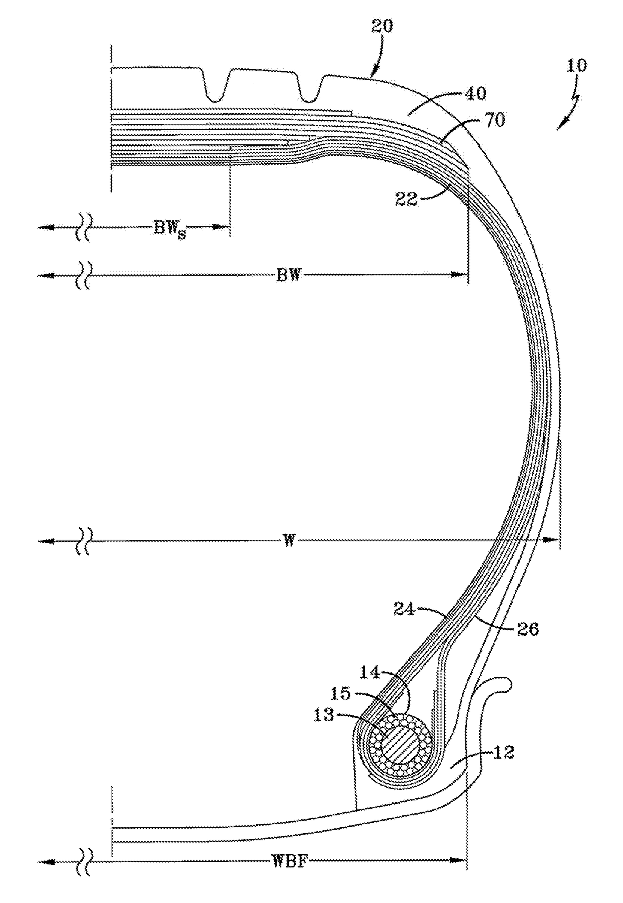
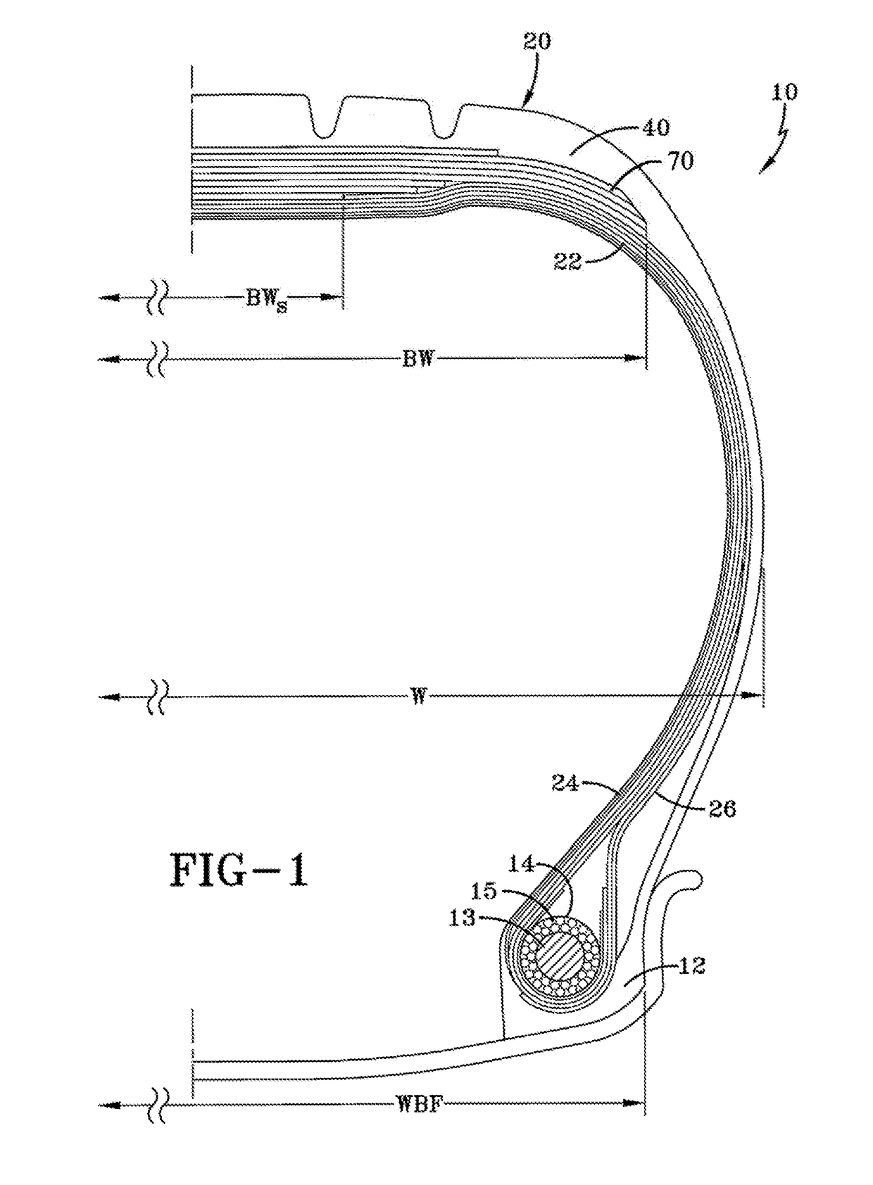
[0021]FIG. 1 illustrates a cross-sectional view of one half of a radial aircraft tire 10 of the present invention. The tire is symmetrical about the mid-circumferential plane so that only one half is illustrated. As shown, the aircraft tire comprises a pair of bead portions 12 each containing a bead core 14 embedded therein. One example of a bead core suitable for use in an aircraft tire is shown in U.S. Pat. No. 6,571,847. The bead core 14 preferably has an aluminum, aluminum alloy or other light weight alloy in the center portion 13 surrounded by a plurality of steel sheath wires 15. A person skilled in the art may appreciate that other bead cores may also be utilized.

[0022]The aircraft tire further comprises a sidewall portion 16 extending substantially outward from each of the bead portions 12 in the radial direction of the tire, and a tread portion 20 extending between the radially outer ends of the sidewall portions 16. The tire is shown mounted on a rim flange having a rim fl...


PUM

PropertyMeasurementUnit
Fractionaaaaaaaaaa
Timeaaaaaaaaaa
Angleaaaaaaaaaa

Abstract

A pneumatic tire having a carcass and a belt reinforcing structure, the belt reinforcing structure comprising: a zigzag belt reinforcing structure formed of a strip of one or more reinforcement cords, the strip of one or more reinforcement cords being inclined at 5 to 30 degrees relative to the centerplane of the tire extending in alternation to turnaround points at each lateral edge, wherein the zigzag strip of cords may be formed from two different reinforcement cords made of different materials, and the lateral edges of the strip are preferably pointed or triangular in shape.

Description

FIELD OF THE INVENTION[0001]This invention relates to pneumatic tires having a carcass and a belt reinforcing structure, more particularly to high speed heavy load tires such as those used on aircraft.BACKGROUND OF THE INVENTION[0002]Pneumatic tires for high speed applications experience a high degree of flexure in the crown area of the tire as the tire enters and leaves the area of the footprint. This problem is particularly exacerbated on aircraft tires wherein the tires can reach speed of over 200 mph at takeoff and landing.[0003]When a tire spins at very high speeds the crown area tends to grow in dimension due to the high angular accelerations and velocity, tending to pull the tread area radially outwardly. Counteracting these forces is the load of the vehicle which is only supported in the small area of the tire known as the footprint area.[0004]Current tire design drivers are an aircraft tire capable of high speed, high load and with reduced weight. It is known in the prior a...

Claims


Application Information

Patent Timeline
IPC IPC(8): B60C9/28B60C1/00B60C9/00B60C9/20
CPCB60C9/28B60C1/0008B60C2200/02B60C9/20B60C9/0057B60C2009/2048B60C9/2009B60C2009/208B60C2009/2096B60C2009/2029B60C9/263B60C2009/266B60C2009/2077B60C2009/2083B60C9/2204B60C9/005B60C9/00B60C2009/209B60C9/22B60C9/0042B60C2009/0078B60C2001/0066
Inventor KMIECIK, FRANK ANTHONYSLIVKA, JOHN JOSEPH
Owner THE GOODYEAR TIRE & RUBBER CO
Why Eureka
Try Eureka