Tie plate for railroad tracks with spike protectors

a technology of rail tracks and protectors, applied in railway fastenings, constructions, roads, etc., can solve the problems of spike cracking, spike breaking at the flexing point, delay in train movement, extensive property damage, etc., and achieve the effect of preventing the generation of deformation zones

Active Publication Date: 2018-03-01
PANDROL LTD
View PDF2 Cites 4 Cited by
  • Summary
  • Abstract
  • Description
  • Claims
  • Application Information

AI Technical Summary

Benefits of technology

[0007]The present invention relates to a railway tie plate that includes rigid hollow cylinders or sleeves that house spikes and prevent the spikes from breaking and prevent the generation of deformation zones in wooden crossties. The present invention does not crush and damage the wood fibers of the ties and does not require frequent re-tightening of spikes, providing an improved long term solution to the problem described above.

Problems solved by technology

This flexing causes cracks in the spike, typically about one to two inches beneath the top surface of the wooden tie.
Eventually, as a result of fatigue, the spike breaks at the flexing point.
Broken spikes are difficult to detect visually even by professional railway track rail inspectors and have resulted in numerous train derailments all over the world, causing death and injuries, as well as extensive property damage and delays in train movements.
As rail shipments of cargo increase, these derailments become increasingly unacceptable, especially if the cargo includes hazardous materials.
Additionally, water and foreign materials, such as dirt and sand, can get into the deformation zones causing damage to the ties, the plate and the spike, reducing the useful life of plates, ties and spikes and requiring more frequent replacements of these components.
Thus, the overall maintenance costs of the respective rails is increased by the breakage of the spikes.
However, these approaches were not very successful because they resulted in crushed and damaged wood fibers, thereby reducing the useful life of the tie.
In addition, the plates settled into the tie over time, requiring the spikes to be re-driven.

Method used


Image

  • Tie plate for railroad tracks with spike protectors
  • Tie plate for railroad tracks with spike protectors
  • Tie plate for railroad tracks with spike protectors

Examples


second embodiment

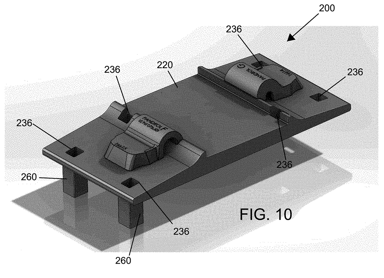
[0042]FIGS. 10 and 11 shows a tie plate assembly 200 that includes a tie plate 220 with a plurality of holes 236 that extend therethrough and sleeves 260 that extends through two of the holes 236. As shown, the holes 236 and sleeves 260 are both substantially square with the sleeves 260 fixed within holes 236 and extend from a first side of the plate 220.

third embodiment

[0043]FIG. 12 shows a tie plate assembly 300 that includes a tie plate 320 that has a plurality of holes 336 that extend therethrough sleeves 360 that extend from two of the holes 336. As shown, the holes 336 and sleeves 360 are both substantially square with one of the sleeves 360 fixed within one of the holes 336 formed in a first side of the plate 320 and another one of the sleeves 362 fixed within one of the holes 336 formed in a second side of the plate 320.

fourth embodiment

[0044]FIG. 13 depicts a tie plate assembly 400 fixed to a tie 14 with a rail 16 secured on the tie plate 420. Here, the tie plate 420 includes a plurality of first holes 436, second holes 438 and third holes 439 with first sleeves 460 extending through the first holes 436, second sleeves 462 extending through the second holes 438 and third sleeves 463 extending through the third holes 437. The straight spikes 40 are arranged snuggly within the first sleeves 460 and threaded spikes 42 are arranged in the second sleeves 462. As can be seen, the sleeves 460, 426 and spikes 40, 42 extend through the plate 420 and into the tie 14 to secure the plate 420 to the tie 14.

[0045]FIG. 14 is a partial cross-sectional view of the tie plate 420 of FIG. 13 showing the sleeves 460, 462 arranged in the first holes 436 and second holes 438, respectively.

[0046]FIG. 15 is a bottom view of FIG. 13 showing the holes 436, 438, 439 and the sleeves 460, 462, 463 arranged in the respective holes 436, 438, 439...


PUM


Abstract

Typically, a tie plate assembly for supporting a rail on a tie includes a tie plate and a spike that is driven through the plate into the tie to secure the tie plate to the point. A sleeve is provided on the plate that is inserted into a tie to prevent the deflection of the spike with respect to the ties wheels of a train pass over the tie.

Description

CROSS-REFERENCE TO RELATED APPLICATION[0001]This patent application claims priority under 35 U.S.C. §119 to U.S. Provisional Patent Application No. 62 / 379,848, filed Aug. 26, 2016, which is hereby incorporated by reference herein in its entirety as part of the present disclosure.FIELD OF THE INVENTION[0002]This patent application pertains generally to railroad rails support systems and more specifically to a plate that supports railroad rails on ties with spikes where the plate is formed with integral sleeves that extend downwardly, receive the spikes and protect the spikes from bending and breaking.BACKGROUND OF THE INVENTION[0003]Steel tie plates and “cut” spikes or other types of spikes have been commonly used to fasten railway rails to wooden crossties since the late 1800s. A vital function of the spikes is to transfer lateral forces from the train wheels to the crossties (or ties) as a train runs over the rails. Over time, a deformation zone can be created in a wooden tie, form...

Claims


Application Information

Patent Timeline
Patent Type & Authority Applications(United States)
IPC IPC(8): E01B9/14E01B9/48
CPCE01B9/14E01B2201/02E01B9/48E01B9/12E01B9/44
Inventor COATS, FRANK HOWARD
Owner PANDROL LTD
Why Eureka
Try Eureka