
Optical path folding element, imaging lens module and electronic device

Active Publication Date: 2018-03-01
LARGAN PRECISION
View PDF8 Cites 66 Cited by
  • Summary
  • Abstract
  • Description
  • Claims
  • Application Information

AI Technical Summary

Benefits of technology

This patent describes an optical path folding element which can be used in an imaging lens module. The element has an incident surface, a path folding surface, and an exiting surface. It uses an engaging structure to fold light rays as they pass through the element. The optical effective portion of the element has an angle between its annular surface portion and its inclined surface portion which satisfies a specific condition. This design allows for compact and efficient imaging lens modules to be made, with improved image quality. It can be used in electronic devices such as smartphones and digital cameras.

Problems solved by technology

However, conventional telephoto lens assembly is limited by surface shapes or materials of lens elements so that the volume cannot be reduced easily and price is too high, and further the application range is limited.

Method used


Image

  • Optical path folding element, imaging lens module and electronic device
  • Optical path folding element, imaging lens module and electronic device
  • Optical path folding element, imaging lens module and electronic device

Examples


1st embodiment

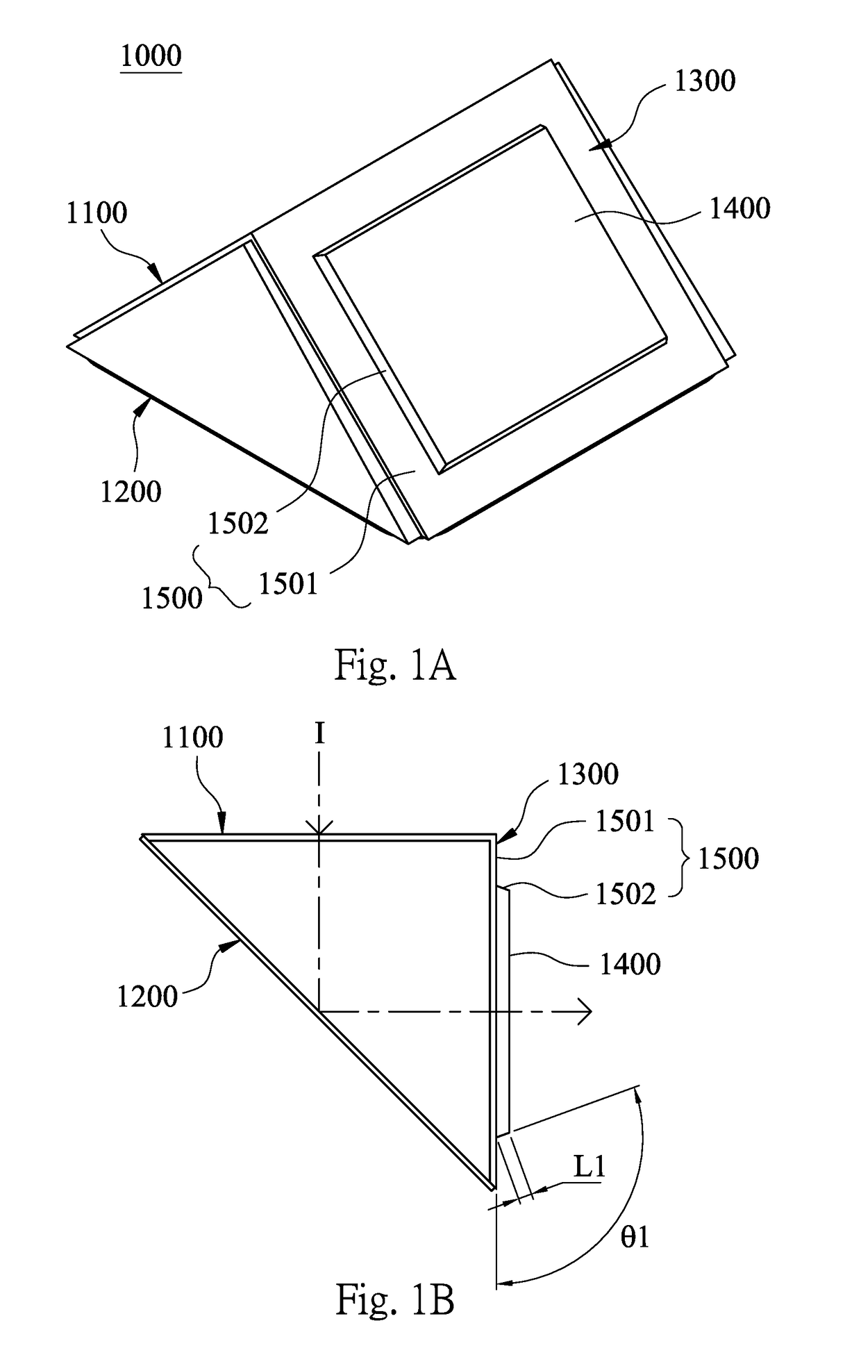
[0045]Please refer to FIG. 1A and FIG. 1B. FIG. 1A is a three dimensional view of an optical path folding element 1000 according to a 1st example of the present disclosure, and FIG. 1B is a cross-sectional view of the optical path element 1000 according to the 1st example of the present disclosure. As shown in FIG. 1A, the optical path folding element 1000 of the 1st example includes an incident surface 1100, a path folding surface 1200 and an exiting surface 1300. The light ray I passes through the incident surface 1100 to enter the optical path folding element 1000. After passing through the path folding surface 1200, the light ray I has a folding angle of 90 degrees and passes through the exiting surface 1300 to depart from the optical path folding element 1000.

[0046]In particular, the optical path folding element 1000 is a triangular prism, and the optical path folding element 1000 is made of a plastic material. Thereby, the optical path folding element 100 can be applied in an ...

2nd example

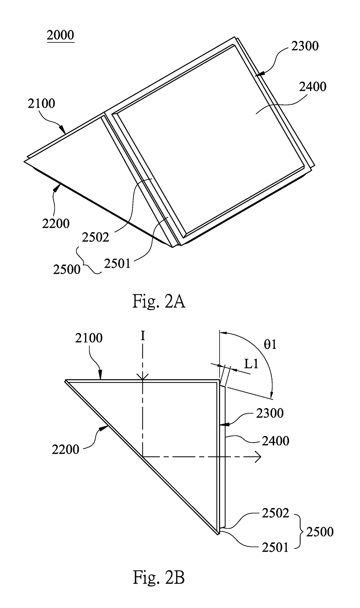
[0051]Please refer to FIG. 2A and FIG. 2B. FIG. 2A is a three dimensional view of an optical path folding element 2000 according to a 2nd example of the present disclosure, and FIG. 2B is a cross-sectional view of the optical path element 2000 according to the 2nd example of the present disclosure. As shown in FIG. 2A, the optical path folding element 2000 of the 2nd example is a triangular prism and includes an incident surface 2100, a path folding surface 2200 and an exiting surface 2300. The light ray I passes through the incident surface 2100 to enter the optical path folding element 2000. After passing through the path folding surface 2200, the light ray I has a folding angle of 90 degrees and passes through the exiting surface 2300 to depart from the optical path folding element 2000.

[0052]In the 2nd example, the exiting surface 2300 of the optical path folding element 2000 includes an optical effective portion 2400 and an engaging structure 2500. In particular, the optical ef...

3rd example

[0056]Please refer to FIG. 3A and FIG. 3B. FIG. 3A is a three dimensional view of an optical path folding element 3000 according to a 3rd example of the present disclosure, and FIG. 3B is a cross-sectional view of the optical path element 3000 according to the 3rd example of the present disclosure. As shown in FIG. 3A, the optical path folding element 3000 of the 3rd example is a triangular prism and includes an incident surface 3100, a path folding surface 3200 and an exiting surface 3300. The light ray I passes through the incident surface 3100 to enter the optical path folding element 3000. After passing through the path folding surface 3200, the light ray I has a folding angle of 90 degrees and passes through the exiting surface 3300 to depart from the optical path folding element 3000.

[0057]In the 3rd example, the exiting surface 3300 of the optical path folding element 3000 includes an optical effective portion 3400 and an engaging structure 3500. It is different from the 1st ...


PUM

PropertyMeasurementUnit
Fractionaaaaaaaaaa
Angleaaaaaaaaaa
Volumeaaaaaaaaaa

Abstract

An optical path folding element includes an incident surface, a path folding surface and an exiting surface. The incident surface allows a light ray to pass into the optical path folding element. The path folding surface folds the light ray from the incident surface. The exiting surface allows the light ray to pass through and depart from the optical path folding element. At least one of the incident surface and the exiting surface includes an optical effective portion and at least one engaging structure symmetrically disposed around the optical effective portion. The engaging structure includes an annular surface portion and an inclined surface portion. The annular surface portion surrounds the optical effective portion, and the inclined surface portion is located between the annular surface portion and the optical effective portion. An angle between the annular surface portion and the inclined surface portion satisfies a specific condition.

Description

RELATED APPLICATIONS[0001]This application claims priority to Taiwan Application Serial Number 105213079, filed Aug. 26, 2016, which is herein incorporated by reference.BACKGROUNDTechnical Field[0002]The present disclosure relates to an optical path folding element and imaging lens module. More particularly, the present disclosure relates to an optical path folding element and imaging lens module for an electronic device.Description of Related Art[0003]Due to the popularity of personal electronic products and mobile communication products having camera functionalities, such as smart phones and tablet personal computers, the demand for compact imaging lens modules has been increasing. However, conventional telephoto lens assembly is limited by surface shapes or materials of lens elements so that the volume cannot be reduced easily and price is too high, and further the application range is limited. Hence, one of the goals in the optical lens industry is to find out how to satisfy mar...

Claims


Application Information

Patent Timeline
IPC IPC(8): G02B13/00G02B1/04G02B17/08
CPCG02B13/0065G02B17/0856G02B1/04G02B5/04G02B6/26G02B17/00G02B17/086G02B19/0028G02B23/243G02B27/0101
Inventor CHOU, MING-TA
Owner LARGAN PRECISION
Features
  • Generate Ideas
  • Intellectual Property
  • Life Sciences
  • Materials
  • Tech Scout
  • Unparalleled Data Quality
  • Higher Quality Content
  • 60% Fewer Hallucinations
Learn More