Scanning MEMS reflector system

a scanning reflector and microelectromechanical technology, applied in wave based measurement systems, optics, instruments, etc., can solve the problems of inability to easily integrate comb-type actuation with silicon beams without significantly increasing the surface area of the actuation system, and the complexity of the capacitive actuator implementation, etc., to achieve the effect of improving the actuation rang

Active Publication Date: 2018-03-01
MURATA MFG CO LTD
View PDF0 Cites 8 Cited by
  • Summary
  • Abstract
  • Description
  • Claims
  • Application Information

AI Technical Summary

Benefits of technology

[0022]An object of the present disclosure is to provide an apparatus and an associated method for overcoming the above problems. In particular, the object of the present disclosure is to present an actuator system for scanning MEMS reflectors wherein an improved actuation range can be obtained on a small surface area.

Problems solved by technology

The principle of mechanical amplification presented in this disclosure can be implemented with both capacitive and piezoelectric actuators, but a capacitive implementation is more complex.
However, the amplitude of the vertical motion generated by this capacitive actuator is limited by the separation gap, which must be on the order of a few μm.
However, comb-type actuation cannot be easily integrated with silicon beams without significantly increasing the surface area of the actuation system.
As seen in FIG. 4 in document WO2015075222, a problem with this prior art solution is that the actuation units (3) require a very large surface area to be able to generate a sufficient actuation range.
The large chip size required of the scanning MEMS reflector disclosed in WO2015075222 limits its versatility.
However, both of these prior-art solutions for mechanical amplification require a great deal of surface area.
They cannot be used with large-area reflectors and they require a large chip size even for small-area reflectors.
Furthermore, neither of them can generate wobbling-mode oscillation.

Method used


Image

  • Scanning MEMS reflector system
  • Scanning MEMS reflector system
  • Scanning MEMS reflector system

Examples


first embodiment

[0043]The first embodiment relates to tilting mode oscillation achieved with actuation units that comprise bending actuators and rigid lever suspenders. In this embodiment the reflector is supported from the frame by suspenders and by a torsion bar.

second embodiment

[0044]The second embodiment relates to wobbling mode oscillation, also achieved with actuation units that comprise bending actuators and rigid lever suspenders. In this embodiment the reflector is attached to the frame only with suspenders.

third embodiment

[0045]The third embodiment relates to actuation units comprising interconnected bending actuators, which can be used in combination with either of the first two embodiments.

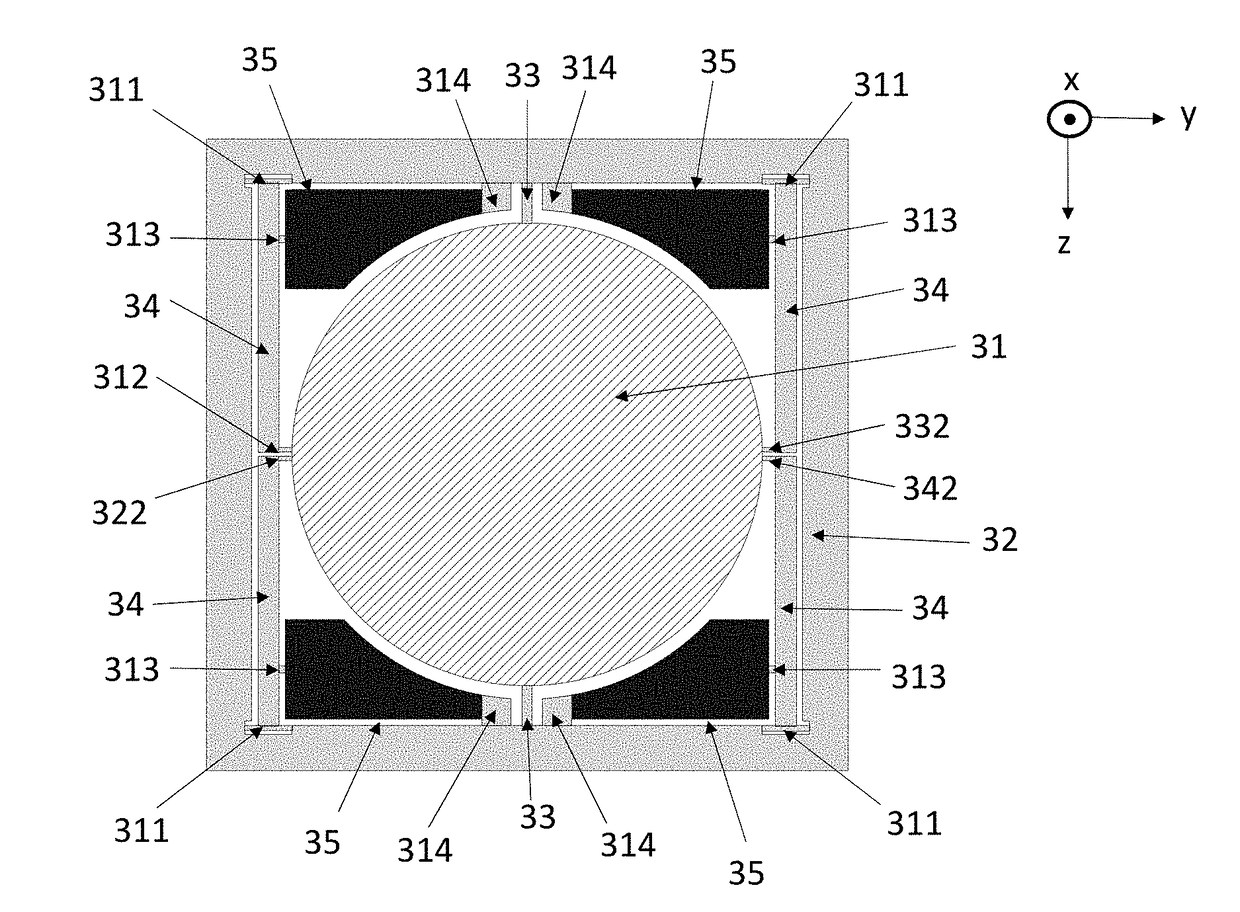
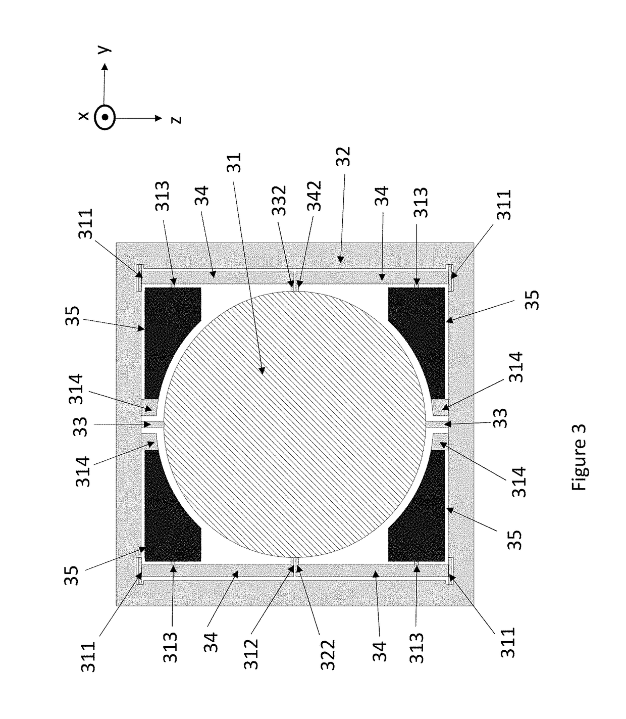
[0046]An actuation system for a scanning MEMS reflector according to the first embodiment is illustrated in FIG. 3. It shows a reflector 31 with a circular shape, surrounded by a frame 32. The reflector 31 is fixed to the frame 32 from a torsion beam 33 which allows tilting mode oscillation of the reflector 31 about the z-axis. As shown in FIG. 3, a first pair of opposing edges of the reflector is fixed to the frame 32 from the torsion beam 33. The torsion beam can, for example, consist of a pair of silicon bridges which are suitably narrow in the y-direction and suitably thin in the x-direction to allow reflector 31 to twist about the z-axis when the reflector is actuated into oscillating motion. The torsion beam must be sufficiently robust to withstand the strain generated in this twisting movement. The optimal...


PUM


Abstract

The actuation range obtained with a bending piezoelectric actuator in MEMS mirror system is mechanically amplified by fixing the moving end of the actuator to a suspender which suspends a reflector from a frame. The fixing point lies somewhere between the two ends of the suspender. The actuator and the suspender together form an actuator unit with a greater actuation range than one actuator can obtain by itself. In one embodiment, the suspender is a rigid lever. In another embodiment, the suspender is another bending actuator so that an additional increase in the actuation range can be obtained from the actuating movement of the second actuator.

Description

FIELD OF THE DISCLOSURE[0001]This disclosure relates to microelectromechanically actuated scanning reflectors.BACKGROUND OF THE DISCLOSURE[0002]Scanning microelectromechanical (MEMS) reflectors can be used in imaging devices such as light-detecting and ranging sensors (LIDARs). A scanning MEMS reflector may contain at least one moving reflector which can reflect light beams from a laser emitter towards the surrounding environment. Additional fixed reflectors may be included in the light path between the moving reflector and the environment. Returning light beams can be reflected inward towards a photodetector by the same fixed reflectors and moving reflector which reflected the outgoing beam.[0003]The imaging area (i.e. the field of view) of a scanning MEMS reflector is in part determined by how much the moving reflector can be tilted. This is illustrated in FIG. 1, which shows a simplified two-dimensional sketch of a reflector system. A laser emitter 11 emits a light beam 111. Movi...

Claims


Application Information

Patent Timeline
Patent Type & Authority Applications(United States)
IPC IPC(8): G02B26/10G02B26/08G01S7/481
CPCG02B26/105G02B26/0858G01S7/4817G02B26/0833G02B26/101
Inventor TORKKELI, ALTTI
Owner MURATA MFG CO LTD
Why Eureka
Try Eureka