Multi-blade shock absorber

a shock absorber and multi-blade technology, applied in the field of multi-blade shock absorbers, can solve the problem that the majority of energy is returned to the balance, and achieve the effect of diffusing the rigidity between the different blades

Active Publication Date: 2018-03-01
MONTRES BREGUET
View PDF10 Cites 0 Cited by
  • Summary
  • Abstract
  • Description
  • Claims
  • Application Information

AI Technical Summary

Benefits of technology

[0018]In another advantageous embodiment the difference in rigidity between the different blades is achieved by differentiating the material between the blades and / or by having elastic blades of different dimensions / shapes.

Problems solved by technology

However, because of the poor mechanical absorption of the metal blades used as anti-shock elements most of the energy is returned to the balance.

Method used


Image

  • Multi-blade shock absorber
  • Multi-blade shock absorber
  • Multi-blade shock absorber

Examples


first embodiment

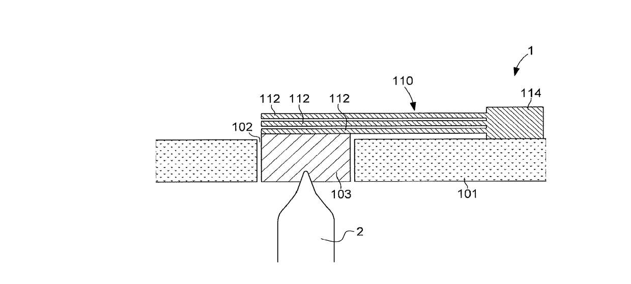
[0030]FIG. 1 shows a shock-absorbing device 1 or anti-shock system according to a This shock-absorbing device or anti-shock system 1 is mounted in a base element 101 or support of a timepiece movement. In particular, the plate or the bridges of the movement are the base element, in which the anti-shock system 1 according to the invention is positioned. This shock-absorbing device is used to absorb the shocks of a staff 2 of a timepiece wheel set: a wheel train or a balance or an escape wheel.

[0031]This base element or support 101 is provided with an opening 102 facing the staff 2 to be damped. The staff 2 cooperates with a pivot element 103. This pivot element 103 can be a pivot stone having a recess so that the pivot shank of the shaft is inserted there. This pivot stone could be freely positioned directly in the opening or via a setting so that it can be displaced at least axially during a shock.

[0032]The shock-absorbing device additionally comprises one of the spring means 110 t...

second embodiment

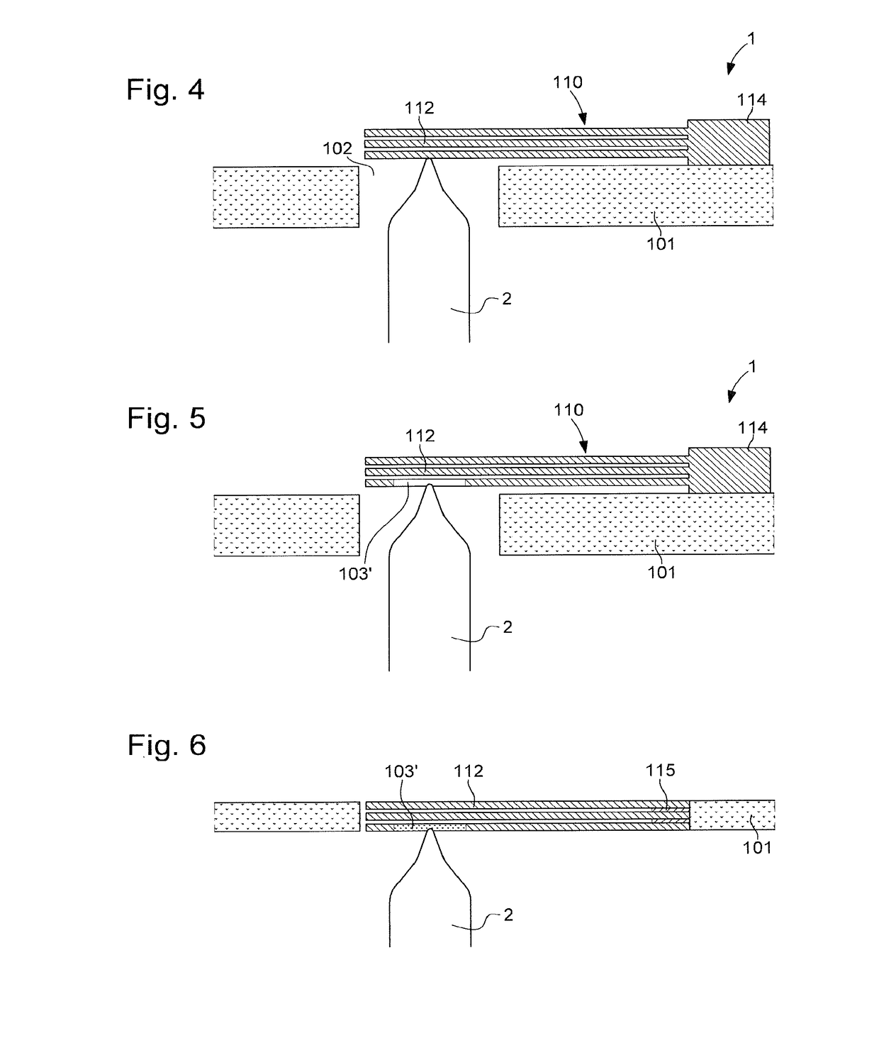
[0046]In a second embodiment the elastic blades 112 are arranged to replace the pivot element 103. This is understood to mean that the elastic blades 112 and the pivot element 103 form a single unit.

[0047]For this, these elastic blades 112 are arranged so that the first blade, i.e. the blade closest to the base element (plate or bridge), serves as pivot element 103. There are two possible solutions for this.

[0048]The first solution evident in FIG. 4 consists of using the first blade 112 directly as pivot element. This is understood to mean that the elastic blade 112 is made from a first material and that the pivot shank of the staff comes into contact with this first material. The elastic blade 112 could be provided with a recess that facilitates placement of the pivot shank of the staff.

[0049]In a second solution evident from FIG. 5 the first elastic blade 112 bears a pivot element 103′. For this, the elastic blade 113 has a hole, either a through hole or not, in which a pivot elem...


PUM


Abstract

The present invention relates to a shock-absorbing device for a staff of a wheel set of a timepiece arranged on a support, wherein said support is provided with an at least partially through slot for a pivot element cooperating with a pivot shank of the staff of the wheel set to be inserted therein, wherein said device additionally comprises a spring means comprising at least a first blade and a second blade.

Description

[0001]This application claims priority from European patent application No. 16186316.2 filed on Aug. 30, 2016, the entire disclosure of which is hereby incorporated herein by reference.[0002]The present invention relates to a shock-absorbing device for a staff of a wheel set of a timepiece arranged on a support, wherein said support is provided with an at least partially through slot for a pivot element cooperating with a pivot shank of the staff of the wheel set to be inserted therein, wherein said device additionally comprises a spring means comprising at least a first blade and a second blade.TECHNOLOGICAL BACKGROUND[0003]There exist shock-absorbing or anti-shock systems in timepieces for protecting the staffs of the wheel sets. A first system is a lyre-type system, i.e. the plate or bridge is provided with a hole, through which the pivot shank of a staff can pass. This hole serves as receptacle for a support that is pierced at its centre, in which a setting is arranged. This set...

Claims


Application Information

Patent Timeline
Patent Type & Authority Applications(United States)
IPC IPC(8): G04B31/04
CPCG04B31/04G04B43/002G04B31/004G04B17/32
Inventor LENOIR, DEIRDRE
Owner MONTRES BREGUET
Why Eureka
Try Eureka