Mower cord and manufacturing method for mower cord

Active Publication Date: 2018-03-08
SANYO TEGUSU
View PDF5 Cites 8 Cited by
  • Summary
  • Abstract
  • Description
  • Claims
  • Application Information

AI Technical Summary

Benefits of technology

[0033]The present invention allows dra

Problems solved by technology

The nylon cord is not sharp in comparison with a metallic rotary blade, and even contac

Method used

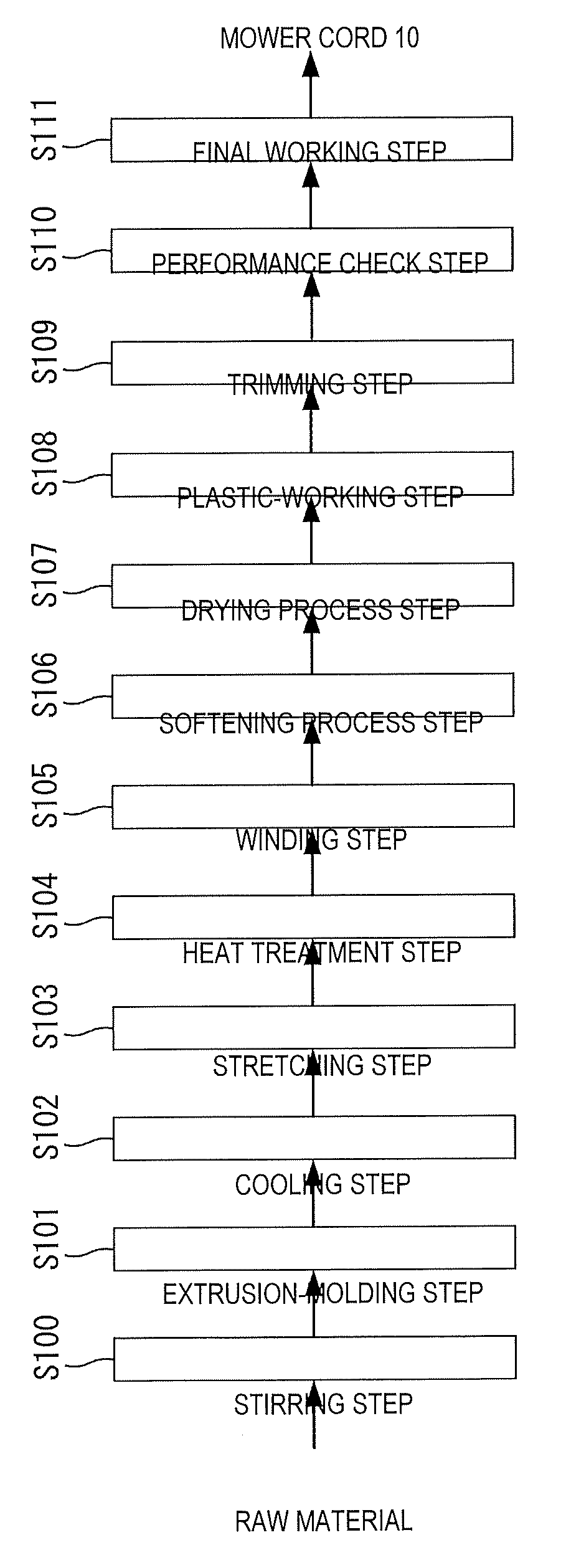
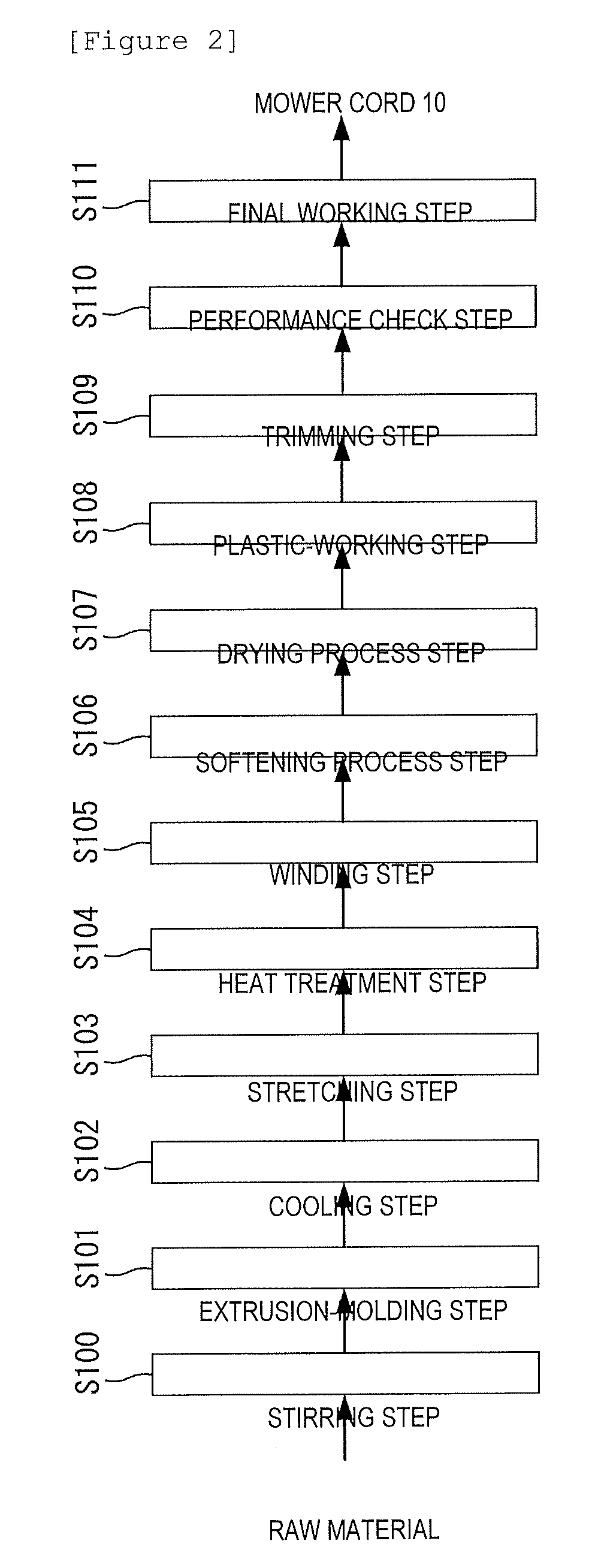

Image

  • Mower cord and manufacturing method for mower cord
  • Mower cord and manufacturing method for mower cord
  • Mower cord and manufacturing method for mower cord

Examples


Embodiment Construction

[0052]A mower cord according to the present invention will be described below in detail with reference to the drawings.

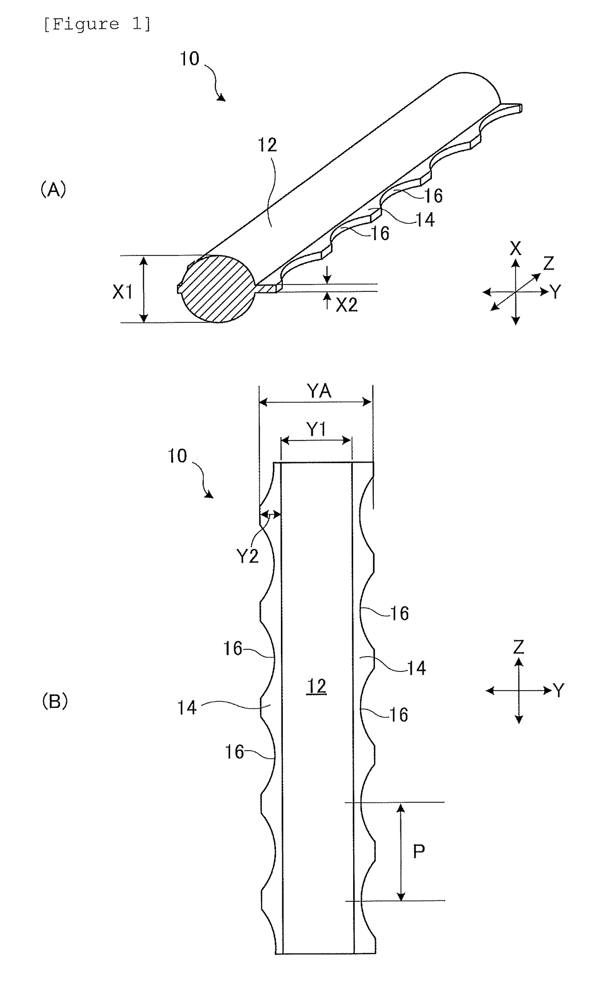
[0053]A mower cord 10 shown in FIG. 1 is used to mow not only grass, such as a lawn, ridge grass, and weeds, but also various plants and trees, such as bamboo grass and twigs. The material for the mower cord 10 is, for example, resin, and a monofilament of synthetic resin is a representative example.

[0054]The mower cord 10 includes a cord-like main body portion 12 and flat portions 14 which are obtained through plastic deformation and are thinner than the main body portion 12. The flat portion 14 is flatter than a wire rod S (see FIG. 2) before plastic deformation of the mower cord 10. Note that the flat portion 14 can also be defined as an extended portion which is expanded and formed so as to protrude from the main body portion 12 toward an outer side in a radial direction. The cross-sectional shape in an axis perpendicular direction of the mower cord 10 is change...


PUM

PropertyMeasurementUnit
Pressureaaaaaaaaaa
Shapeaaaaaaaaaa
Widthaaaaaaaaaa

Abstract

The present invention relates to a manufacturing method for a mower cord and includes pressing a resin wire rod and plastically deforming at least part of the wire rod in an axis perpendicular direction. Work-hardening of a surface of the plastically deformed portion allows dramatic enhancement of mowing efficiency.

Description

TECHNICAL FIELD[0001]The present invention relates to a mower cord or the like used in a cord type mowing apparatus.BACKGROUND ART[0002]There has recently been known a nylon cord which is used while being attached to an outer periphery of a rotating component, such as a disc, in a mowing apparatus (see, for example, Japanese Patent Laid-Open No. 2007-135418). The nylon cord cuts away grass while whirling due to rotation of the rotating component and is coming into widespread use instead of a metallic rotary blade. The nylon cord is not sharp in comparison with a metallic rotary blade, and even contact of a human body with the whirling nylon cord is unlikely to result in serious injury. The nylon cord can be replaced in accordance with the extent of breakage or abrasion and is easy to replace.[0003]To improve the mowing capability of such a nylon cord, the idea of making a cross-section in an axis perpendicular direction (a transverse section) quadrangular or rhombic, or the idea of ...

Claims


Application Information

Patent Timeline
IPC IPC(8): A01D34/416A01D34/73B26F1/12B29C43/02B29C55/00
CPCA01D34/4168A01D34/73B26F1/12B29C43/021B29C55/00B29C43/02B29C48/00B29C43/226B29C43/22B29C43/224B29C43/222
Inventor ISHIKAWA, TOSHIOICHIKAWA, SHIGEKISUZUKI, MASAYA
Owner SANYO TEGUSU
Why Eureka
Try Eureka