Bug killing gun

a technology of bug-killing guns and bullets, which is applied in the field of bug-killing guns, can solve the problems of leaving potentially harmful chemical residues in the area where used, and achieve the effect of reducing the risk of infection

Active Publication Date: 2018-03-08
MAGGIORE LOREN
View PDF0 Cites 5 Cited by
  • Summary
  • Abstract
  • Description
  • Claims
  • Application Information

AI Technical Summary

Benefits of technology

[0020]The main pole is attached to the piston, has an upwardly angled ramp at a rear end, located behind the control notch. The ramp guides the rib into the control notch. The main pole moves rearwardly in a channel in the supporting stock during the cocking action. The releasing bracket retains the main pole in a first, cocked position as the rib engages the control notch. The bracket releases the main pole to a second, fired position as the trigger is moved rearwardly, elevating the releasing bracket and raising the rib from the control notch. This allows the main pole and the piston to move forward as urged by the compression spring, pressurizing the cylinder.
[0025](9) In another variant of the invention, the projectile loading mechanism further includes a mid-chamber pipe. The pipe extends downwardly from a lower end of the magazine. A lower portion of the pipe provides a stop for one end of a return compression spring. A trajectory guide is provided. The guide is located below the lower end of the magazine, has a hollow bore sized to fit slidably about the pipe and has a vertical slot that extends downwardly from the lower end for a first predetermined distance. The slot terminates in a stopping surface. The trajectory guide is located about the pipe and provides a support platform for attachment of the projectile storage magazine. A metering rod is provided. The rod is cylindrical in shape and is sized to fit slidably within the pipe and has an orthogonal activation bar extending from its lower end. The metering rod has a through hole located above the activation bar. The through hole is orthogonal to the bar and the metering rod and is sized and located to align with the chamber when the bar is positioned against the stopping surface. The return compression spring urges the metering rod upwardly to rest against the lower end of the vertical circular opening in the chamber. A subordination pole is provided. The pole has a first end and a second end and is pivotally mounted to a cover for the compressed gas source. The first end of the subordination pole includes a metering slot. The metering slot surrounds the activation bar. The second end of the subordination pole is urged upwardly by a cam upon activation of the gas release mechanism. Upward movement of the second end of the subordination pole moves the activation bar downwardly, compresses the return compression spring and aligns the through hole of the metering rod with the chamber. This permits the compressed gas to drive the particulate projectiles out of the chamber and through the barrel. Downward movement of the second end of the subordination pole causes the activation bar to move upwardly as urged by the return compression spring. This allows the particulate projectiles to fill the through hole of the metering rod as it moves in the projectile storage magazine surrounded by the particulate projectiles.
[0027](11) In yet another variant, a downward pointing cam lobe is provided. The cam lobe is located beneath and orthogonal to the metering slot. A cam activating tab is provided. The tab is located adjacent to a side edge and front end of an upper surface of the primary gear rack. The activating tab has a contoured inner surface. The contoured inner surface is sized, shaped and located to engage a front edge of the cam lobe as the primary gear rack is moved rearwardly and forwardly during operation of the cocking mechanism. Engagement of the cam lobe causes upward movement of the metering rod followed by downward movement of the metering rod during operation of the cocking mechanism. Such movement serving to dislodge any particulate projectiles adhering to the metering rod.
[0046](23) In yet another variant of the invention, a pistol grip and a forearm of the support stock have flattened lower surfaces. The flattened surfaces permit the bug killing gun to be balanced in an upright position for adding the particulate projectiles to the projectile storage magazine.

Problems solved by technology

The former requires a certain skill and agility to be effective and the latter leaves a potentially harmful chemical residue in the area where used.

Method used


Image

  • Bug killing gun
  • Bug killing gun
  • Bug killing gun

Examples


Embodiment Construction

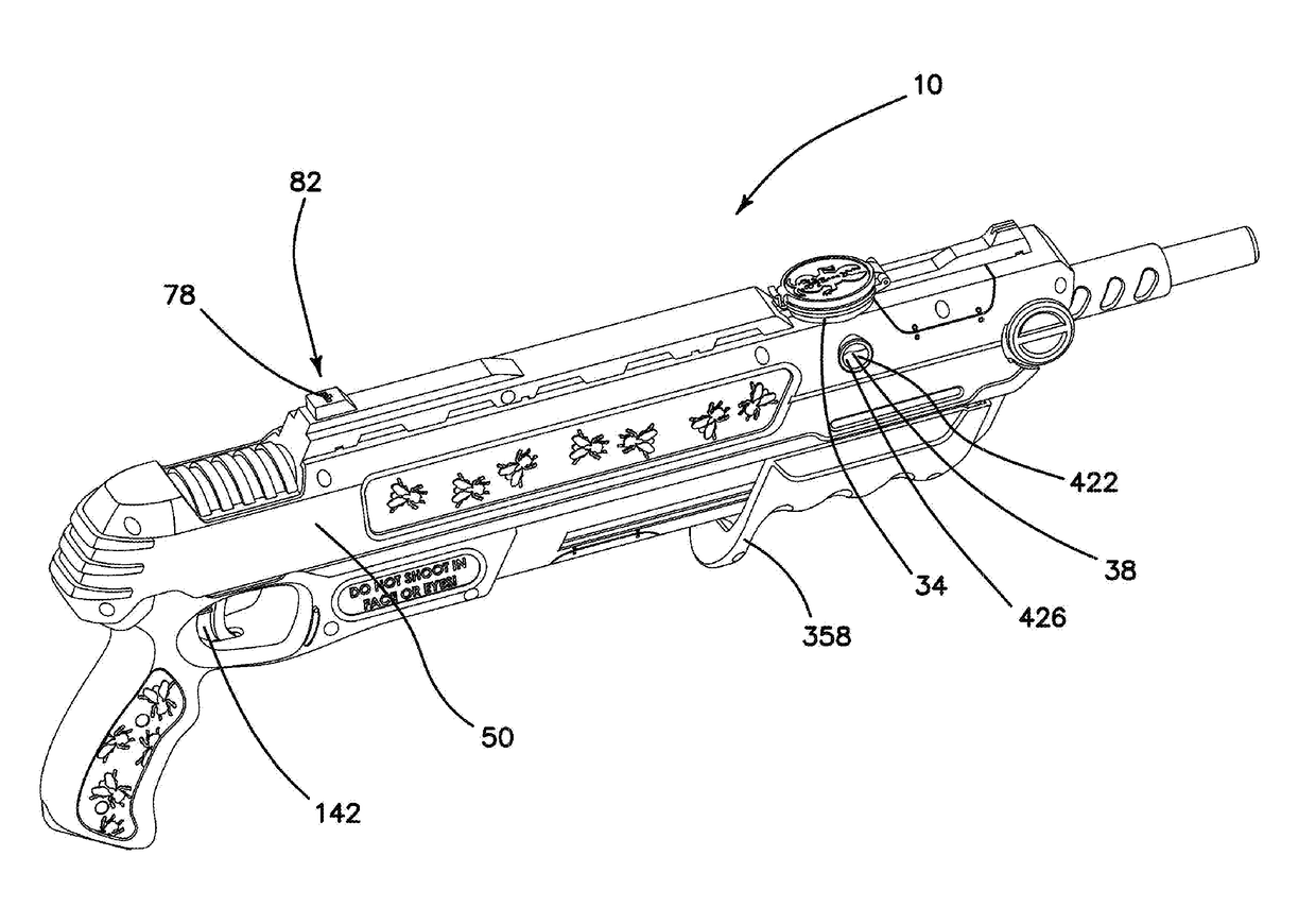
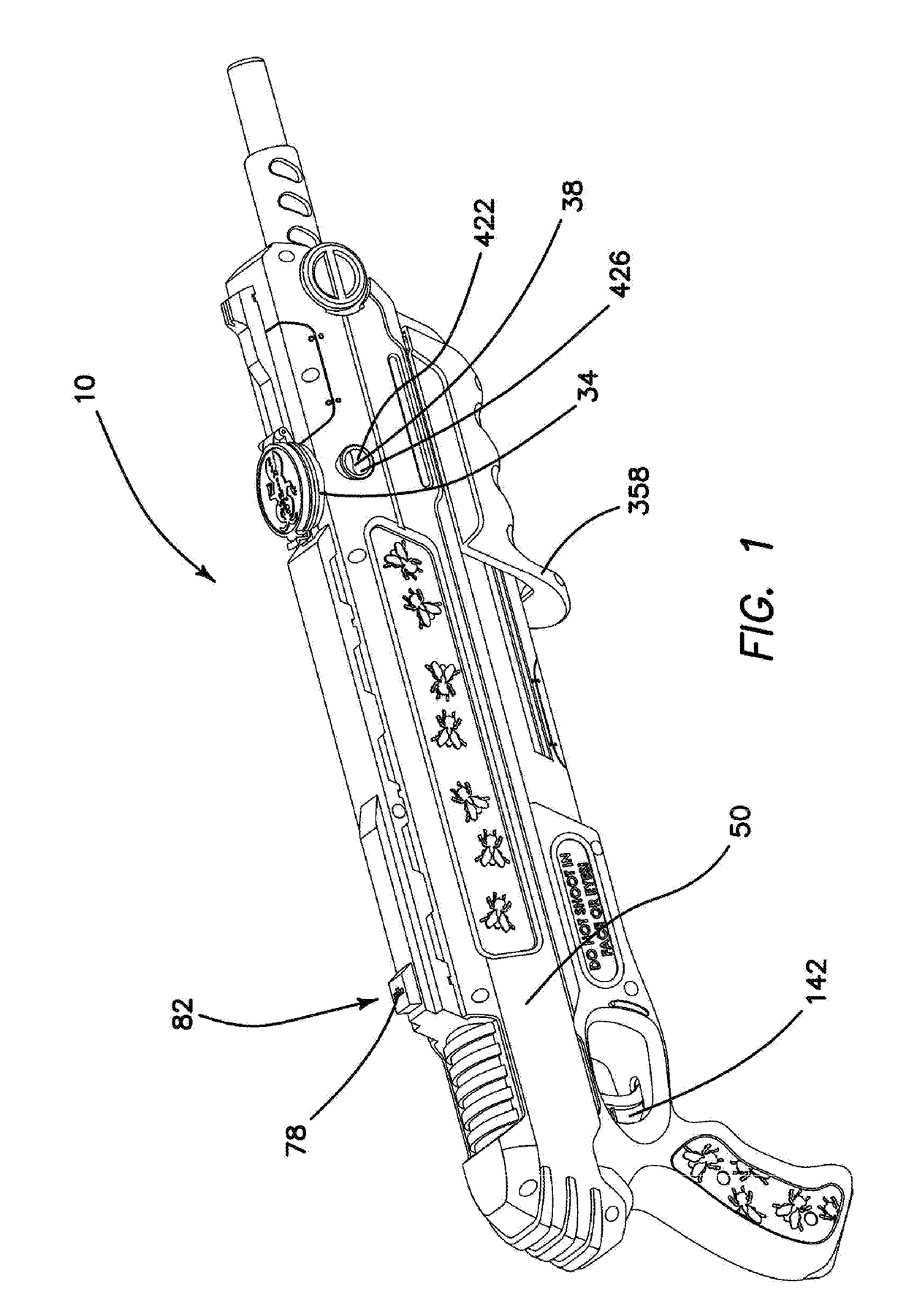
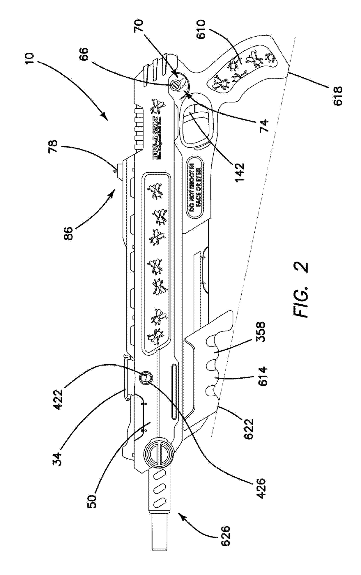
[0080](1) FIGS. 1-11 illustrate an improved bug killing gun 10 providing the desired features that may be constructed from the following components. As illustrated in FIGS. 10 and 11, a compressed gas source 14 is provided. A chamber 18 is provided. The chamber 18 is fluidly connected to the compressed gas source 14. A barrel 22 is provided. The barrel 22 is located at a distal end 26 of the chamber 18. As illustrated in FIGS. 5 and 6, a compressed gas release mechanism 30 is provided. The release mechanism 30 is connected to the compressed gas source 14. As illustrated in FIGS. 1-4, 10 and 11, a projectile storage magazine 34 is provided. The magazine 34 stores particulate projectiles 38 and is located adjacent the chamber 18. A projectile loading mechanism 42 is provided. The loading mechanism 42 moves the particulate projectiles 38 into the chamber 18 from the magazine 34. A cocking mechanism 46 is mechanically connected to the compressed gas source 14, the compressed gas release...


PUM


Abstract

An improved bug killing gun includes a compressed gas source fluidly connected to a chamber connected to a barrel. A compressed gas release mechanism is connected to the compressed gas source. A projectile storage magazine stores particulate projectiles and is located adjacent the chamber. A projectile loading mechanism moves the projectiles into the chamber from the magazine. A cocking mechanism is mechanically connected to the compressed gas source, the compressed gas release mechanism, and the projectile loading mechanism. When the gun is cocked, the projectile loading mechanism loads a quantity of the particulate projectiles into the chamber. When the compressed gas release mechanism is activated the projectiles are ejected from the chamber into the barrel and expelled from the gun. The gun optionally includes a laser sighting mechanism. The battery operated laser sighting mechanism may be removably attached to the barrel or permanently attached with an integral, trigger operated switch.

Description

PRIOR APPLICATION[0001]The present application is a continuation of International Application No. PCT / US2016 / 039268, filed Jul. 29, 2016 and incorporates the disclosure of which in its entirety.FIELD OF INVENTION[0002]This invention relates to the fields of weaponry and insect control, and more specifically to a device for killing insects at a distance without use of toxic chemicals.BACKGROUND OF THE INVENTION[0003]Many methods and devices have been developed for dealing with insect pests. Many people are particularly interested in dealing with flying insects as they tend to be very visible, sometimes noisy and often possessing the capability to bite or sting. Traditional means for killing flying insects include devices such as fly swatters and their equivalent or chemical sprays. The former requires a certain skill and agility to be effective and the latter leaves a potentially harmful chemical residue in the area where used. The present invention addresses these concerns and also ...

Claims


Application Information

Patent Timeline
Patent Type & Authority Applications(United States)
IPC IPC(8): A01M27/00F41B11/52F41B11/68F41B11/62F41G3/08F41G1/35
CPCA01M27/00F41B11/52F41B11/68F41B11/62F41G3/08F41G1/35F41B11/80A01M3/00F41B11/682F41B11/681A01M3/027F41A17/48F41B11/646F41B11/51
Inventor MAGGIORE, LOREN
Owner MAGGIORE LOREN
Why Eureka
Try Eureka