Improved glenoid anchor for a shoulder joint prosthesis

Active Publication Date: 2018-03-08
LIMA CORPORATE SPA
View PDF7 Cites 10 Cited by
  • Summary
  • Abstract
  • Description
  • Claims
  • Application Information

AI Technical Summary

Benefits of technology

[0023]Essentially, with the solution according to the present invention it is envisaged that the pin portion of the anchor element is designed separately from the associated flange, which is instead formed integrally in the solutions of the prior art, and is provid

Problems solved by technology

Although advantageous in many respects and substantially fulfilling their purpose, all these known solutions have a common drawback consisting in the fact they are not always able to ensure correct and durable fixing of the anchor element inside the glenoid cavity, with obvious serious risks of slackening and/or separation.
In particular, the presence of the flange formed as one piece with the pin portion of the anchor element is a limitation for the surgeon who must correctly form in the glenoid cavity the seat for the pin portion, making sure, however, to position it so that the flange may adhere with a form-fit to the surface of the glenoid cavity.
Moreover, the form of these anchor e

Method used


Image

  • Improved glenoid anchor for a shoulder joint prosthesis
  • Improved glenoid anchor for a shoulder joint prosthesis
  • Improved glenoid anchor for a shoulder joint prosthesis

Examples


Embodiment Construction

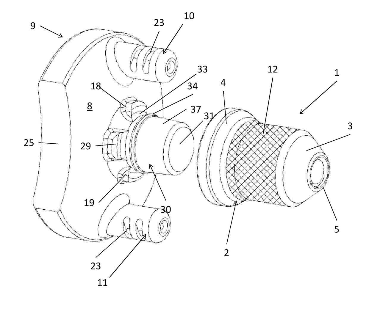
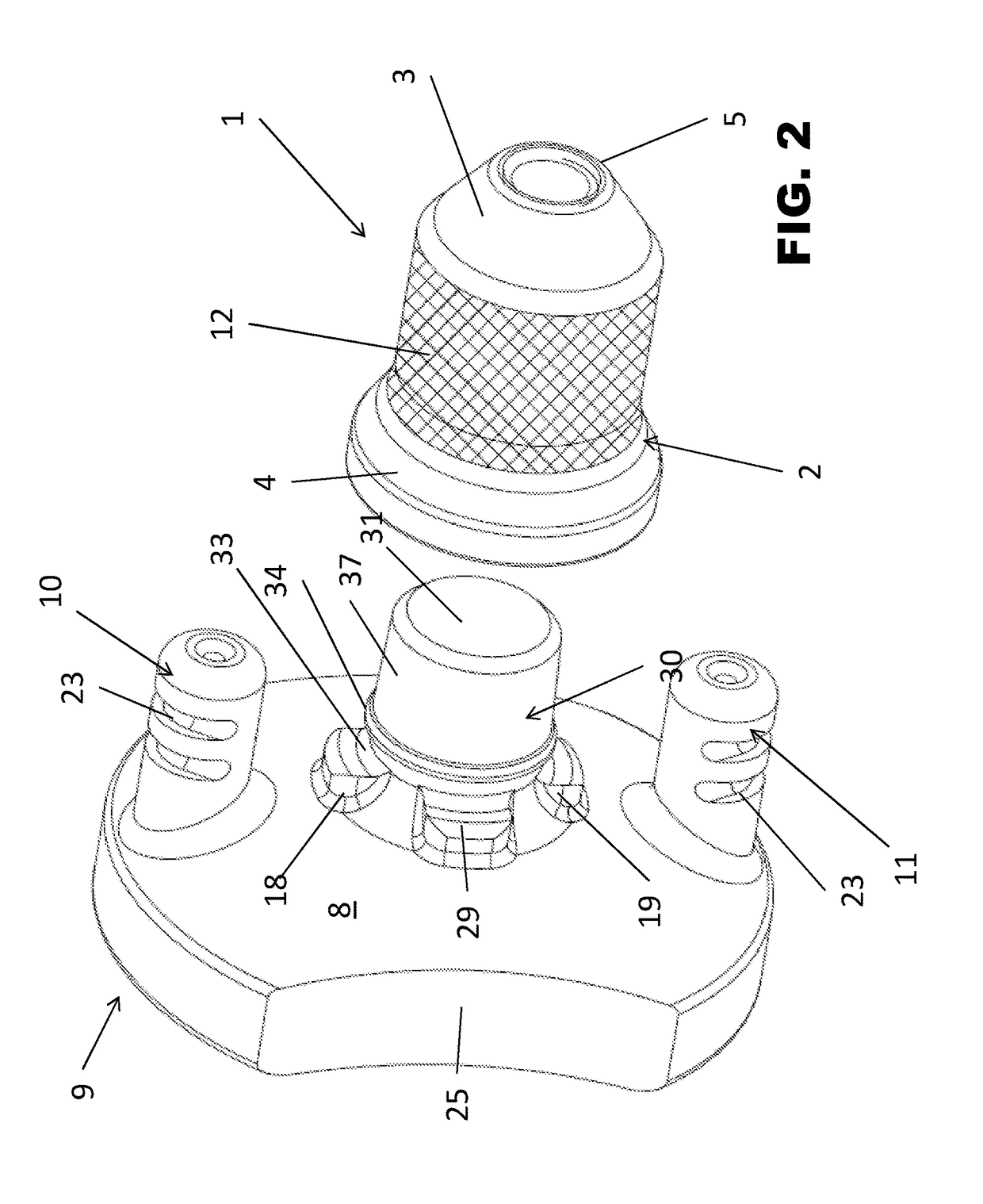
[0042]With reference to these figures, and in particular to the example shown in FIG. 2, 1 denotes overall and in schematic form an improved anchor element designed in accordance with the present invention for stably and securely fixing a prosthesis for the shoulder joint to the glenoid cavity of the shoulder blade.

[0043]In the description below reference will be made to this anchor element 1 using the simpler term “glenoid anchor”.

[0044]Advantageously the anchor 1 is a component which allows the conversion of a shoulder joint prosthesis from an anatomical prosthesis to a reverse prosthesis. This anchor 1 is intended to cooperate with another, structurally independent, prosthesis component 9, which can be snap-engaged by means of a mechanical interference fit with the anchor 1 and which will be described in greater detail below.

[0045]The anchor 1 is intended to be surgically implanted in the glenoid cavity of the shoulder blade and has the function of supporting the loads and of bei...


PUM


Abstract

The present invention relates to an improved glenoid anchor for a shoulder joint prosthesis, in particular a convertible prosthesis, of the type intended to be fixed to the glenoid cavity of the shoulder blade and comprising:—a pin (2) with an internally hollow and essentially thimble-like conical sleeve (12), which has a tapered distal end (3) and an open proximal end (4);—an annular recess (15) formed inside the cavity (13) of the pin (2) in the vicinity of said open proximal end (4), for receiving by means of snap-engagement an edge (34) of a lug (30) of a prosthesis component (9);—at least one pair of oppositely arranged anti-rotation notches (16, 17) in the proximity of said annular groove (15) for receiving by means of snap fit oppositely arranged teeth (18, 19) of the same lug (30) intended to be snap-engaged together with said pin (2).

Description

FIELD OF APPLICATION[0001]The present invention relates to an improved glenoid anchor for a prosthesis of the shoulder joint, in particular a hybrid prosthesis, namely a convertible prosthesis.[0002]The invention relates more specifically, but not exclusively, to an accessory anchor element which allows stable and secure fixing of prosthesis for articulation of the shoulder with the glenoid cavity of the shoulder blade and conversion of this prosthesis from an anatomical prosthesis to a reverse prosthesis; the description which follows is provided with reference to this specific field of application in order to simplify description thereof.PRIOR ART[0003]As is well-known, shoulder prostheses which reproduce in a more or less natural manner the glenohumeral anatomy are regularly used. These prostheses are defined as being anatomical and comprise an anchor element or glenoid insert which is fixed to the shoulder blade, inside the glenoid cavity.[0004]The prostheses have a glenoid and ...

Claims


Application Information

Patent Timeline
IPC IPC(8): A61F2/30A61F2/40
CPCA61F2/30749A61F2/4081A61F2002/30336A61F2002/30349A61F2002/30367A61F2002/305A61F2002/30507A61F2002/30878A61F2002/4085A61F2002/30332A61F2310/00023
Inventor PRESSACCO, MICHELEFATTORI, ANDREAVIDONI, GABRIELECONNER, PATRICK MICHAELIZQUIERDO, ROLANDOPOON, PETER CHANNELSCALISE, JASON J.
Owner LIMA CORPORATE SPA
Why Eureka
Try Eureka