Inkjet recording apparatus

a recording apparatus and inkjet technology, applied in the field of inkjet recording apparatuses, can solve the problems of poor fixability of photo-curable ink to recording medium, difficult to effect high-quality printing, poor fixability of photo-curable ink, etc., to improve the fixability of ink layer to recording medium, improve the quality of ink layer, and improve the effect of ink layer

Active Publication Date: 2018-03-08
ROLAND DG CORP
View PDF3 Cites 5 Cited by
  • Summary
  • Abstract
  • Description
  • Claims
  • Application Information

AI Technical Summary

Benefits of technology

[0006]Accordingly, preferred embodiments of the present invention provide inkjet recording apparatuses that enhance adhesion between a primer layer and a recording medium.
[0007]The inventors of preferred embodiments of the present invention conducted extensive research and discovered a solution involving discharging primer onto a recording medium so as to form a primer layer, and then further discharging primer onto the primer layer and the recording medium so as to form another primer layer, thus enhancing adhesion of the primer layers to the recording medium.
[0009]An inkjet recording apparatus according to a preferred embodiment of the present invention is constructed such that the first controller forms the first primer layer on the recording medium, the second controller forms the second primer layer on the first primer layer and the recording medium, and the third controller forms the image-forming ink layer (which may hereinafter be simply referred to as an “ink layer”) on the second primer layer. Forming the second primer layer on the first primer layer and the recording medium in this manner enhances adhesion between the first primer layer and the recording medium. Forming the ink layer on the second primer layer improves the ink layer in quality and increases fixability of the ink layer to the recording medium.
[0010]Various preferred embodiments of the present invention provide inkjet recording apparatuses that enhance adhesion between a primer layer and a recording medium.

Problems solved by technology

Photo-curable ink, however, has poor fixability to such a recording medium, making it difficult to effect high-quality printing.
Thus, the inkjet recording apparatus is able to suitably effect high-quality printing on a recording medium to which photo-curable ink has poor fixability.
Although fixability of an ink layer to a recording medium is increased by forming a primer layer on the recording medium and forming the ink layer on the primer layer, adhesion between the recording medium and the primer layer may be insufficient depending on how the primer layer is formed.
Even if a high-quality ink layer is formed on a primer layer, insufficient adhesion between the primer layer and recording medium may unfortunately cause the primer layer to be peeled off the recording medium.

Method used


Image

  • Inkjet recording apparatus
  • Inkjet recording apparatus
  • Inkjet recording apparatus

Examples


first preferred embodiment

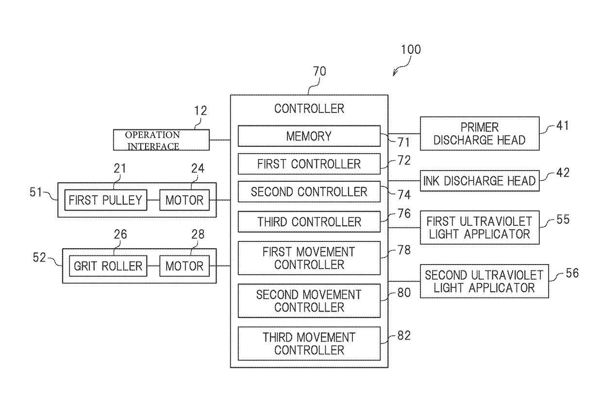
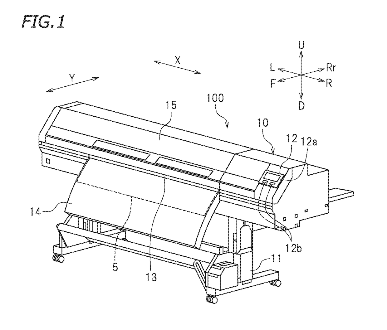
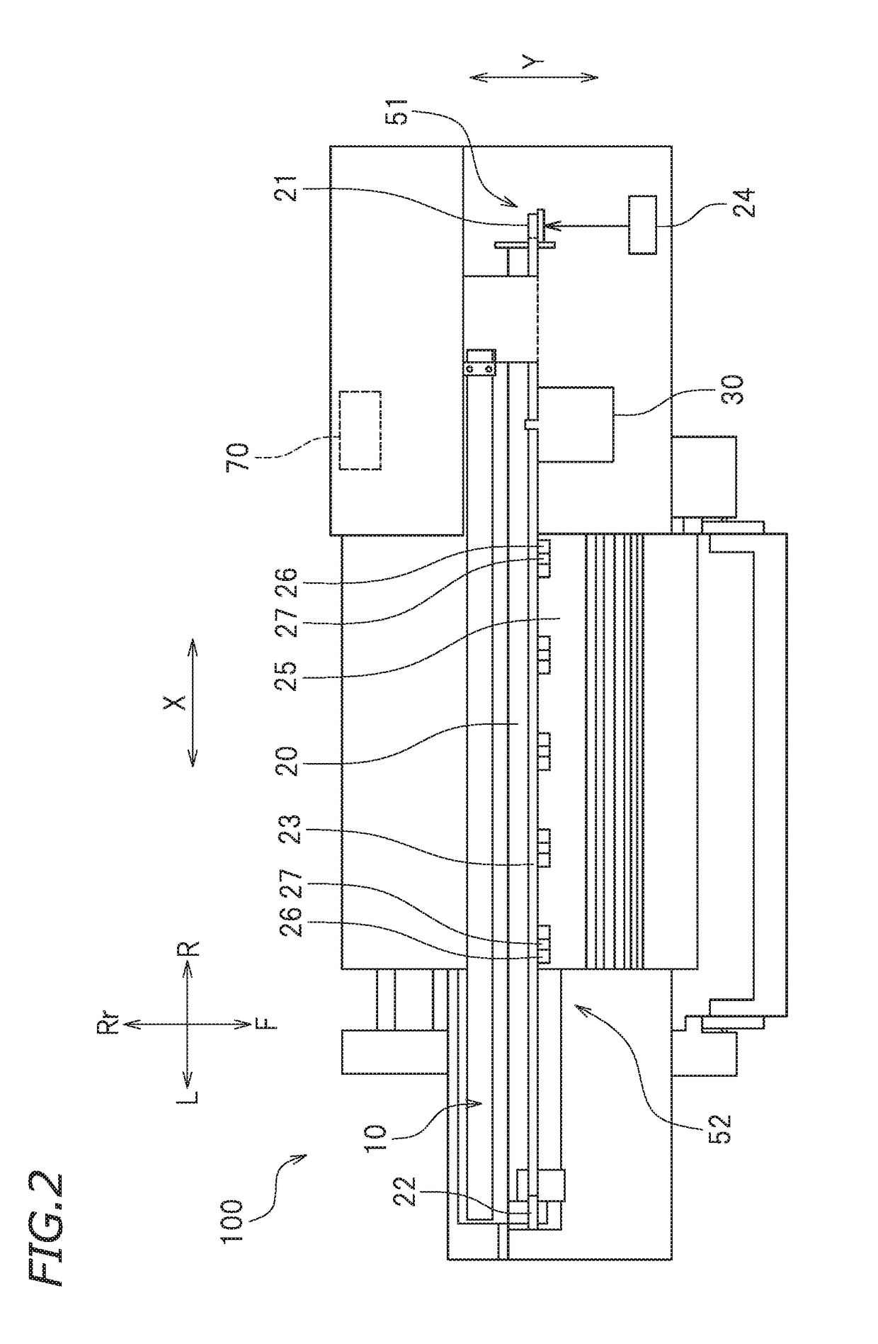
[0022]FIG. 1 is a perspective view of the printer 100 according to a first preferred embodiment of the present invention. The terms “right”, “left”, and “down” in the following description respectively refer to right, left, up, and down with respect to an operator facing the front of the printer 100. The direction away from the printer 100 and toward the operator corresponds to a forward direction. The direction away from the operator and toward the printer 100 corresponds to a rearward direction. The reference signs “F”, “Rr”, “R”, “L”, “U”, and “D” in the drawings respectively represent front, rear, right, left, up, and down. The reference sign X in the drawings represents a main scanning direction. In this preferred embodiment, the main scanning direction X is a right-left direction. The main scanning direction X corresponds to the width direction of a recording medium 5. The reference sign Y in the drawings represents a sub-scanning direction. The sub-scanning direction Y is a d...

second preferred embodiment

[0063]FIG. 8 is a bottom view of the head 40 according to a second preferred embodiment of the present invention. As illustrated in FIG. 8, the head 40 further includes a primer discharge head 43. In this preferred embodiment, the primer discharge head 41 discharges a first primer, and the primer discharge head 43 discharges a second primer. The second primer discharged from the primer discharge head 43 is different in composition from the first primer discharged from the primer discharge head 41. Alternatively, the first primer and the second primer used in the second preferred embodiment may each be similar to the primer used in the first preferred embodiment. In one example, primer having the property of being highly adhesive to the recording medium 5 is preferably used as the first primer, and primer having the property of being highly fixable to the ink layer 66 is preferably used as the second primer. The second primer preferably contains a surface conditioner including a cros...

third preferred embodiment

[0068]FIG. 9 is a bottom view of the head 40 according to a third preferred embodiment of the present invention. The first ultraviolet light applicator 55 is in engagement with a guide rail 31A provided on the carriage 30. The first ultraviolet light applicator 55 is attached to a first driving belt (not illustrated) provided on the carriage 30. Running of the first driving belt enables the first ultraviolet light applicator 55 to move in the sub-scanning direction Y. The second ultraviolet light applicator 56 is in engagement with a guide rail 31B provided on the carriage 30. The second ultraviolet light applicator 56 is attached to a second driving belt (not illustrated) provided on the carriage 30. Running of the second driving belt enables the second ultraviolet light applicator 56 to move in the sub-scanning direction Y. This structure makes it possible to change the positions of the first ultraviolet light applicator 55 and the second ultraviolet light applicator 56 relative t...


PUM

PropertyMeasurementUnit
diameteraaaaaaaaaa
diameteraaaaaaaaaa
diameteraaaaaaaaaa

Abstract

A printer includes a first controller to cause a primer discharge head to discharge, from its nozzle, primer onto a recording medium and then cause a first ultraviolet light applicator to apply ultraviolet light to the primer, thus forming a first primer layer on the recording medium; a second controller to cause the primer discharge head to discharge, from its nozzle, the primer onto the first primer layer and the recording medium and then cause a second ultraviolet light applicator to apply ultraviolet light to the primer, thus forming a second primer layer on the first primer layer and the recording medium; and a third controller to cause an ink discharge head to discharge, from its nozzle, image-forming ink onto the second primer layer and then cause the first ultraviolet light applicator to apply ultraviolet light to the image-forming ink, thus forming an ink layer on the second primer layer.

Description

CROSS REFERENCE TO RELATED APPLICATIONS[0001]This application claims the benefit of priority to Japanese Patent Application No. 2016-173013 filed on Sep. 5, 2016. The entire contents of this application are hereby incorporated herein by reference.BACKGROUND OF THE INVENTION1. Field of the Invention[0002]The present invention relates to inkjet recording apparatuses.2. Description of the Related Art[0003]An inkjet printer that uses photo-curable ink (which may hereinafter be simply referred to as a “photo-curing printer”) is known. A photo-curing printer discharges photo-curable ink from a discharge head and applies light to the ink discharged. Thus, the ink is rapidly cured and forms an ink layer on a recording medium so as to print a desired image on the recording medium.[0004]In one example, a photo-curing printer may effect printing on a non-ink-absorbing recording medium, such as a resin material or a metal material. Photo-curable ink, however, has poor fixability to such a recor...

Claims


Application Information

Patent Timeline
Patent Type & Authority Applications(United States)
IPC IPC(8): B41J11/00B41J2/01
CPCB41J2/01B41J11/002B41M3/008B41M5/0011B41M7/0081B41J11/0015B41J11/00214B41J11/00218
Inventor TAKASUGI, MASAHIROYAGI, TAKESHIKATO, MITSUHIROISHIHARA, MASANORI
Owner ROLAND DG CORP
Why Eureka
Try Eureka