Panel and panel structure for ventilation and both reactive and dissipative sound dampening

a technology of ventilation panels and panels, applied in the field of ventilation panels, can solve the problems of lack of acoustic privacy, insufficient air exchange, and aesthetic disorientation

Active Publication Date: 2018-03-08
VANAIR DESIGN
View PDF27 Cites 7 Cited by
  • Summary
  • Abstract
  • Description
  • Claims
  • Application Information

AI Technical Summary

Benefits of technology

[0007]It is an object of the present invention to provide a passive ventilation panel and system, in particular for use in doors, ceilings, walls and partitions, which enables an exchange of supply and return

Problems solved by technology

If a space becomes essentially “airtight”, this air exchange does not adequately occur without costly “active” ventilation methods.
W

Method used


Image

  • Panel and panel structure for ventilation and both reactive and dissipative sound dampening
  • Panel and panel structure for ventilation and both reactive and dissipative sound dampening
  • Panel and panel structure for ventilation and both reactive and dissipative sound dampening

Examples


Embodiment Construction

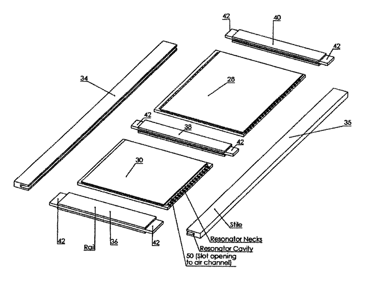
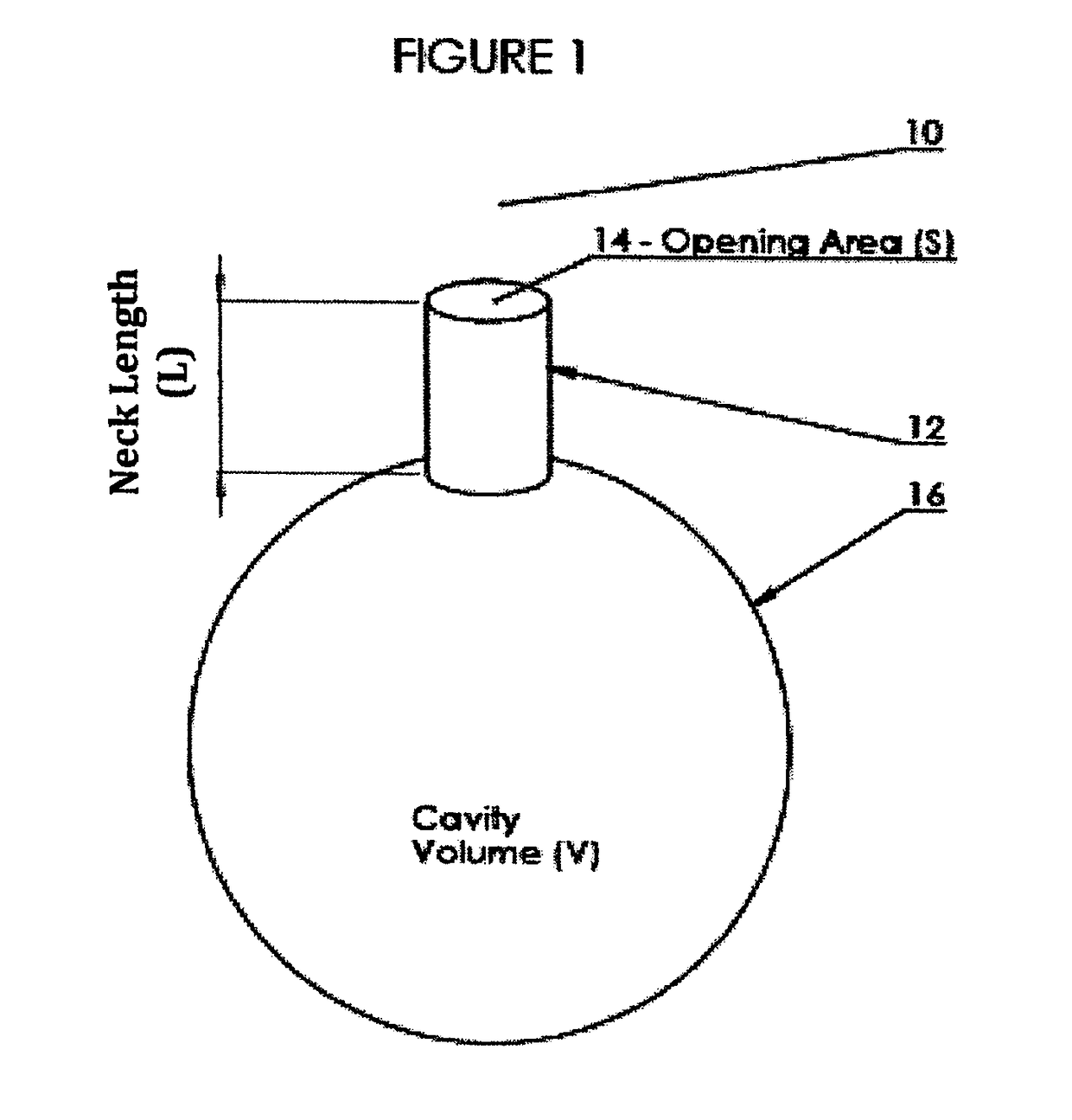
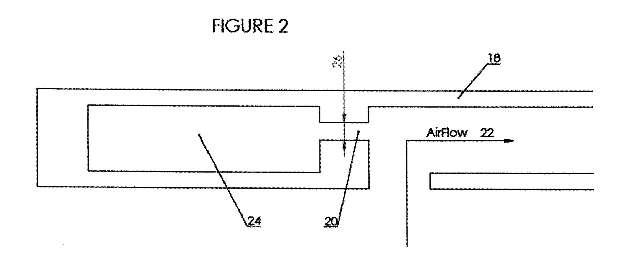
[0064]A detailed description of one or more embodiments of the invention is provided below along with accompanying figures that illustrate the principles of the invention. As such this detailed description illustrates the invention by way of example and not by way of limitation. The description will clearly enable one skilled in the art to make and use the invention, and describes several embodiments, adaptations, variations and alternatives and uses of the invention, including what we presently believe is the best mode for carrying out the invention. It is to be clearly understood that routine variations and adaptations can be made to the invention as described, and such variations and adaptations squarely fall within the spirit and scope of the invention.

[0065]In other words, the invention is described in connection with such embodiments, but the invention is not limited to any embodiment. The scope of the invention is limited only by the claims and the invention encompasses numer...


PUM


Abstract

A passive ventilation panel and system, in particular for use in doors, ceilings, walls and partitions enables an exchange of supply and return air for at least one room or a room, without the need for additional ventilation equipment, such as ducts, and without the needs to install wall openings or grills for the supply and exhaust air in the space.

Description

FIELD OF THE INVENTION[0001]The present invention relates to the field of ventilation panels for use in doors, walls, ceilings and partitions.BACKGROUND ON THE INVENTION[0002]The primary function of interior walls, partitions and doors is to divide building space into separate, private spaces. In construction, there have been, over the past 5-10 years increasing demands for and efficiencies in the development of closed spaces which are sound insulated. With regards to walls, when additional thermal and / or acoustic insulation is needed, insulation medium such as fibreglass, rock wool or mineral wool will commonly be placed to fill the interior space between vertical studs and gypsum board panels. Sound transmission through walls can be reduced by widening the wall and staggering the studs such that no stud spans the full width of the wall.[0003]For the occupants of such spaces, while reduction in sound transmission and heat / AC efficiencies are important, even more important planning ...

Claims


Application Information

Patent Timeline
IPC IPC(8): E04C2/52E04B1/86E04F13/075E04F13/077E04C2/34E06B5/20E06B7/10E06B3/70
CPCE04C2/526E04B1/86E04F13/075E04F13/077E04C2/34E06B5/20E06B7/10E06B3/7015E04B2001/8263E04C2002/3488E06B2003/7023E06B2003/7059E06B2003/7061E04B2/7409E04C2/523F24F13/0227G10K11/172E04B2001/8452F24F2013/242F24F2013/245
Inventor YAU, VICKING WAI KINGHIGGINS, JAMES
Owner VANAIR DESIGN
Why Eureka
Try Eureka