Force-shunting device and mechanical actuator comprising such a device

a technology of force-shunting device and mechanical actuator, which is applied in the direction of belt/chain/gearing, aircraft transmission means, undercarriage, etc., can solve the problems of unsuitable aircraft equipment, high cost, outside forces, etc., and achieve the effect of reliable and cost-effectiveness

Active Publication Date: 2018-03-08
FLY BY WIRE SYST FRANCE
View PDF3 Cites 0 Cited by
  • Summary
  • Abstract
  • Description
  • Claims
  • Application Information

AI Technical Summary

Benefits of technology

[0006]The aim of the invention is consequently to propose a new force-shunting device and a new mechanical actuator comprising such a device, which makes it possible to obta...

Problems solved by technology

The implementation of such a steered device requires the installation, configuration and upkeep of steering means, which represents a certain cost and is a source of potential failures.
However, in...

Method used


Image

  • Force-shunting device and mechanical actuator comprising such a device
  • Force-shunting device and mechanical actuator comprising such a device
  • Force-shunting device and mechanical actuator comprising such a device

Examples


Embodiment Construction

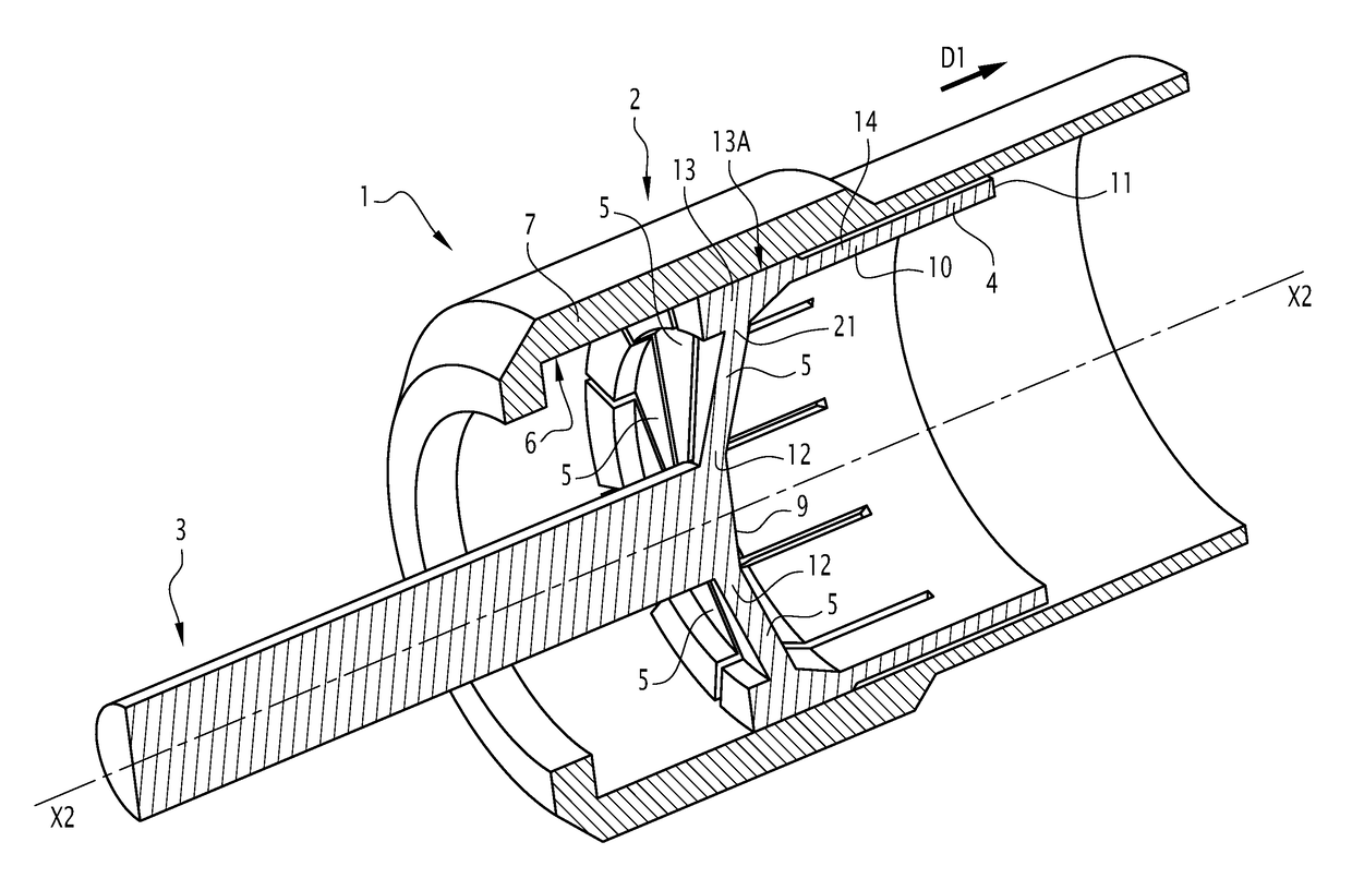
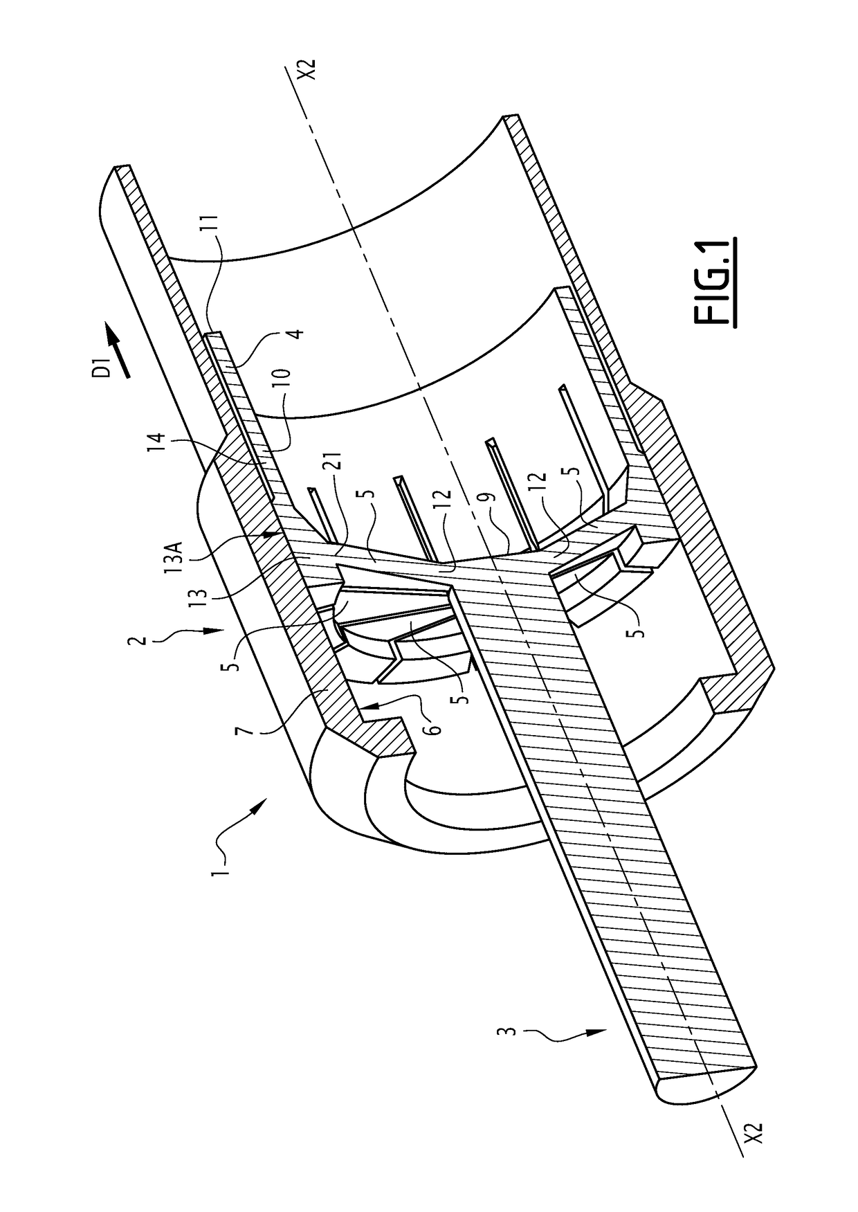
[0031]FIG. 1 shows a force-shunting device 1 that comprises a tube 2, a first member 3, a second member 4 and a plurality of primary legs 5. The example embodiment of FIG. 1 will be taken in the context of an aircraft, and more specifically in the case where the device 1 is implemented in a mechanism for deploying and retracting the landing gear of the aircraft.

[0032]The tube 2 extends along a main axis X2, which preferably forms its axis of revolution. The tube 2 thus for example forms an annular sleeve, the axis of which is coaxial to the main axis X2. The tube 2 has an inner wall 6, which in turn is preferably cylindrical and coaxial to the main axis X2, but which may also have a prismatic or frustoconical shape. The inner wall 6 forms a friction wall and is therefore formed by a friction-resistant material, for example a metal material. The tube 2 has a general construction that allows the inner wall 6 to withstand frictional forces, and radial forces relative to the main axis X...


PUM


Abstract

A force-shunting device including a tube defining a main axis and an inner wall, a first member sliding within the tube, a primary leg arranged obliquely, attached to the first member and including a primary pad in frictional contact with the inner wall, such that, when an external force is applied in a first direction on the first member, the primary leg rubs, or grips by mechanical camming, against the inner wall, the tube thus reacting all or part of the external force, the device including a second member mounted within the tube, sliding along the main axis and securely provided with a driving element of the primary pad so as to reduce the friction on the inner wall, to unprime the rubbing or mechanical camming.

Description

CROSS REFERENCE TO RELATED APPLICATIONS[0001]This application claims priority under 35 USC §119 of French Patent Application No. 16 58353 filed on Sep. 8, 2016.FIELD OF THE INVENTION[0002]The present invention relates to a force-shunting device, as well as a mechanical actuator comprising such a device.[0003]The invention relates to the general field of axial mechanical actuators, and in particular when they are implemented in the aeronautics field. On many aircraft, of the airplane or helicopter type, different types of axial mechanical actuators are installed making it possible to command the position or the orientation of various mechanical devices, for example aerodynamic flight surfaces, or retractable landing gear. In some cases, in particular in the case of a landing gear mechanism, it is necessary to provide means for locking the actuators in a specific position. Indeed, the forces supplied by the axial actuator during the deployment or retraction of the landing gear are low...

Claims


Application Information

Patent Timeline
IPC IPC(8): F16H25/20B64C25/26B64C25/20B64C13/28
CPCF16H25/2021B64C25/26F16H2025/204B64C13/28B64C25/20F16H2035/005F16H25/2454F16H35/10F16D2127/004F16D51/00F16D63/008B64C13/30B64C13/32
Inventor ROUSSEY, BASTIEN
Owner FLY BY WIRE SYST FRANCE
Why Eureka
Try Eureka