Fully reciprocal atomic interferometric gyroscope

a gyroscope and atomic interferometer technology, applied in the direction of gyrometers with sagnac effect, turn-sensitive devices, etc., can solve the problems of measurement errors in the output of the gyroscope, the cost of manufacture is much more expensive than the cost of atomic interferometer based devices

Active Publication Date: 2018-03-08
HONEYWELL INT INC
View PDF1 Cites 16 Cited by
  • Summary
  • Abstract
  • Description
  • Claims
  • Application Information

AI Technical Summary

Benefits of technology

[0005]In one embodiment, a fully reciprocal atomic interferometric gyroscope is provided. The fully reciprocal atomic interferometric gyroscope includes an atomic chamber, a plurality of lasers, a controller and measurement sensor. The atomic chamber is used to hold an atom cloud. The plurality of lasers are selectively positioned to selectively direct laser beams into the atomic chamber. The controller is configured to control the plurality of lasers to initially cool the atom cloud to a point where at least one optical lattice can be formed that is used to move wave function halves of the atoms of the atom cloud along split wave function paths that form an interferometer cycle. The measurement sensor is configured to conduct a phase readout of a wave function upon the completion of at least one interferometer cycle around the split wave function paths.
[0006]In another embodiment, a method of forming a fully reciprocal atomic interferometric gyroscope is provided. The method includes cooling atoms of an atomic cloud held in a chamber. Once cooled, each atom is split into a first atomic wave function half and a second atomic wave function half at a point of separation. At least one optical lattice is used to move the first atomic wave function half along a first split wave function path and the second atomic wave function half along a second split wave function path in a first direction along a plane that is transverse to a rotation axis along which rotation sensing is desired. The first split wave function path and the second split wave function path are caused to intersect with each other to complete a first half of an interferometer cycle a select distance from the point of separation. The at least one optical lattice is used at least in part to move the first atomic wave function half along the second split wave function path and the second atomic wave function half along the first split wave function path in a second direction along the plane back to the point of separation to complete an interferometer cycle. A phase readout is conducted after at least one complete interferometer cycle.
[0007]In yet another embodiment, another method of forming a fully reciprocal atomic interferometric gyroscope is provided. The method includes cooling atoms of an atom cloud held in a chamber until an optical lattice can be formed. A first optical lattice is used to move an atomic wave function of atoms of the cooled atom cloud in a first direction along a plane that is transverse to a rotational axis along which rotation sensing is desired. Each atom is split into a first atomic wave function half and a second wave function half at a point of separation. A pair of overlapping second optical lattices are used to control a separation distance of the first atomic wave function half from the second wave function half so the first atomic wave function half travels along a first split wave function path and the second wave function half travels along a second wave function path in the first direction. The pair of overlapping second optical lattices cause the first split wave function path and the second wave function path to intersect to complete a first half of an interferometer cycle at an intersection point that is a select distance from the point of separation. Upon reaching the intersection point, the first optical lattice is used to change movement of the first atomic wave function half and the second wave function half in a second direction that is opposite the first direction and using the pair of overlapping second optical lattices to cause the first atomic wave function half to move along the second split wave function path and the second atomic wave function half to move along the first split wave function path back to the point of separation to complete an interferometer cycle. A phase readout is then conducted.

Problems solved by technology

High precision gyroscopes using other inertial sensor technologies exist, but they are appreciably more expensive to manufacture than atomic interferometer based devices.
One problem with atomic interferometer devices, however, is that factors other than rotation can affect the phase differences in the split waves accumulated before recombination, leading to measurement errors in the output of the gyroscope.

Method used


Image

  • Fully reciprocal atomic interferometric gyroscope
  • Fully reciprocal atomic interferometric gyroscope
  • Fully reciprocal atomic interferometric gyroscope

Examples


example embodiments

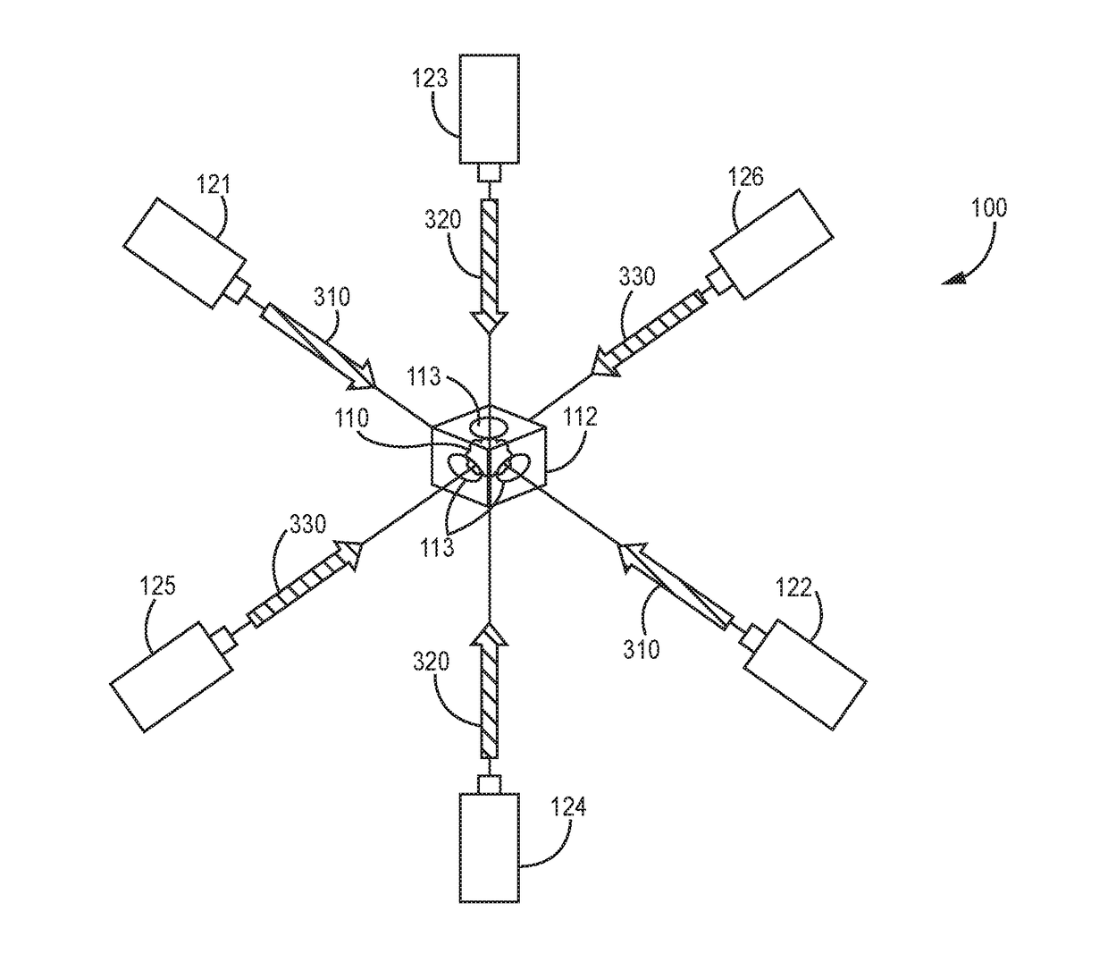
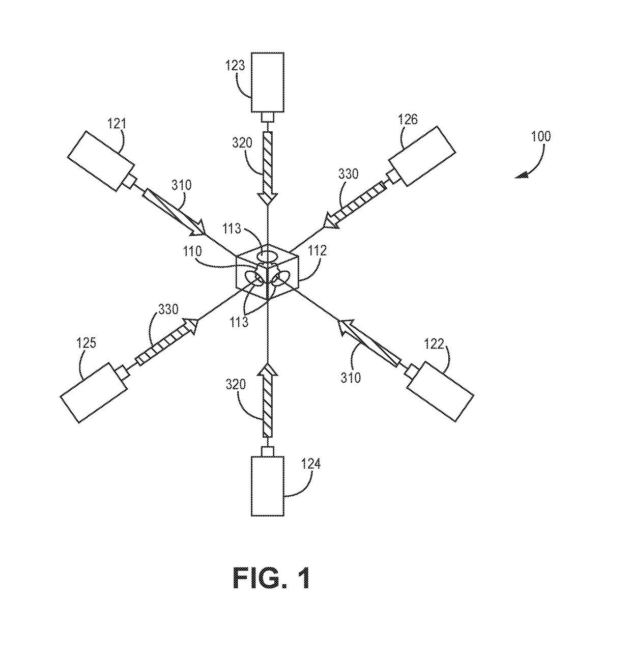
[0045]Example 1 includes a fully reciprocal atomic interferometric gyroscope. The fully reciprocal atomic interferometric gyroscope includes an atomic chamber, a plurality of lasers, a controller and measurement sensor. The atomic chamber is used to hold an atom cloud. The plurality of lasers are selectively positioned to selectively direct laser beams into the atomic chamber. The controller is configured to control the plurality lasers to initially cool the atom cloud to a point where at least one optical lattice can be formed that is used to move wave function halves of atoms of the atom cloud along split wave function paths that form an interferometer cycle. The measurement sensor is configured to conduct a phase readout of a wave function upon the completion of at least one interferometer cycle around the split wave function paths.

[0046]Example 2 includes the fully reciprocal atomic interferometric gyroscope of Example 1, further comprising a plurality of orthogonally oriented w...


PUM


Abstract

A fully reciprocal atomic interferometric gyroscope is provided. The fully reciprocal atomic interferometric gyroscope includes an atomic chamber, a plurality of lasers, a controller and measurement sensor. The atomic chamber is used to hold an atom cloud. The plurality of lasers are selectively positioned to selectively direct laser beams into the atomic chamber. The controller is configured to control the plurality lasers to initially cool the atom cloud to a point where at least one optical lattice can be formed that is used to move wave function halves of atoms of the atom cloud along split wave function paths that form an interferometer cycle. The measurement sensor is configured to conduct a phase readout of a wave function upon the completion of at least one interferometer cycle around the split wave function paths.

Description

CROSS-REFERENCE TO RELATED APPLICATIONS[0001]This Application claims priority to U.S. Provisional Application Ser. No. 62 / 382,894, same title herewith, filed on Sep. 2, 2016, which is incorporated in its entirety herein by reference.BACKGROUND[0002]Atomic interferometer based gyroscopes represent a possible route to high stability rotation sensing that can provide navigation solutions in situations where satellite based navigation has become degraded or is not available. In an atomic interferometer, the wave equation for an atom is split in half and the interferometer causes the two halves of that wave to travel different paths. The two halves are then recombined. When the halves are recombined, the two wave halves may have accumulated a relative phase difference with respect to each other so that a phase measurement can be measured from an output of the interferometer. High precision gyroscopes using other inertial sensor technologies exist, but they are appreciably more expensive ...

Claims


Application Information

Patent Timeline
Patent Type & Authority Applications(United States)
IPC IPC(8): G01C19/64
CPCG01C19/64G01C19/58
Inventor COMPTON, ROBERT
Owner HONEYWELL INT INC
Why Eureka
Try Eureka