Optical system for generating any-order optical vortex array and limited optical lattice with defects
An optical vortex and optical system technology, applied in the field of optics, can solve the problems of complex amplitude modulation, single modulation of light waves, etc., and achieve the effect of saving experimental equipment and space, strong applicability and flexibility, and simple optical path.
- Summary
- Abstract
- Description
- Claims
- Application Information
AI Technical Summary
Problems solved by technology
Method used
Image
Examples
Embodiment 1
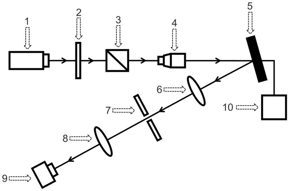
[0043] The laser 1 emits a linearly polarized beam with a wavelength of 632.8nm. After passing through the half-wave plate 2 and the polarization beam splitter 3, the polarization direction of the light is horizontally polarized. The outgoing light enters the beam expander 4 along the light propagating direction, and the beam expander 4 expands the beam. The diameter of the expanded spot is about 3 mm, which can match the liquid crystal panel of the spatial light modulator 5 .
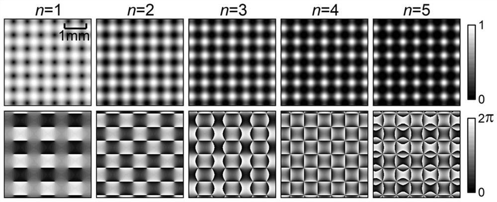
[0044] The light beam expanded by the beam expander 4 is irradiated to the spatial light modulator 5, and the spatial light modulator 5 is controlled by a computer 10, and can load a hologram of an alternating optical vortex array of any order in real time. After complex amplitude modulation by the spatial light modulator 5 and focusing by the first lens 6, the first-order diffracted beam is selected by the diaphragm 7, that is, an arbitrary-order alternating optical vortex array of the target is obtain...
Embodiment 2
[0051] Using the same optical path diagram and complex amplitude encoding method as in Embodiment 1, changing the values of parameters n, a and b, loading the obtained hologram on the spatial light modulator 5, and obtaining different parameters on the image detector 9. tunable finite light lattice.
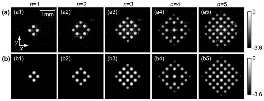
[0052] Figure 4 It is the light intensity distribution experiment result diagram of the tunable finite light lattice produced under different parameters, and the light intensity value is taken as the common logarithm, where: Figure 4 (a)n=3, Figure 4 (b) n=4; parameter w 0 The value of 1.5mm. according to Figure 4 (a1), 4(a3), 4(a5), 4(b1), 4(b3) and 4(b5), it can be found that when the values of parameters a and b are equal, a square finite light lattice is produced array. From Figure 4 In (a2), 4(a4), 4(b2) and 4(b4), it can be seen that when the values of parameters a and b are not equal, a rhombic finite optical lattice array or a rhombic defected Finite Li...
PUM
 Abstract
Description
Claims
Application Information
 - R&D
- Intellectual Property
- Life Sciences
- Materials
- Tech Scout
- Unparalleled Data Quality
- Higher Quality Content
- 60% Fewer Hallucinations
Browse by: Latest US Patents, China's latest patents, Technical Efficacy Thesaurus, Application Domain, Technology Topic, Popular Technical Reports.
© 2025 PatSnap. All rights reserved.Legal|Privacy policy|Modern Slavery Act Transparency Statement|Sitemap|About US| Contact US: help@patsnap.com


