Method and device for liquid cooling of electric motor

a technology of liquid cooling and electric motor, which is applied in the direction of cooling/ventilation arrangement, electrical appliances, dynamo-electric machines, etc., can solve the problems of high air content in the cooling liquid, direct affecting the performance of the active parts of the electric motor, and risking the damage of the motor

Inactive Publication Date: 2018-03-08
BAE SYSTEMS HAGGLUND AKTIEBOLAG
View PDF6 Cites 11 Cited by
  • Summary
  • Abstract
  • Description
  • Claims
  • Application Information

AI Technical Summary

Benefits of technology

[0009]An object of the present invention is to provide a method and a device for liquid cooling of an electric motor th

Problems solved by technology

Cooling of active parts of the electric motor directly affects the performance.
The stator winding often comprises a coated isolated conductor and a known problem of cooling devices wherein a liquid cooling medium is flushed directly onto the coil ends is erosion.
The often statically applied stream of cooling liquid erodes the coating of the stator winding within the application surface which eventually risks damaging the motor.
A problem with the cooling device in GB 170946 and other cooling device wh

Method used


Image

  • Method and device for liquid cooling of electric motor
  • Method and device for liquid cooling of electric motor
  • Method and device for liquid cooling of electric motor

Examples


first embodiment

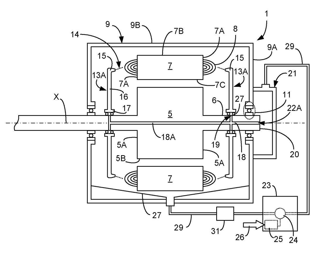
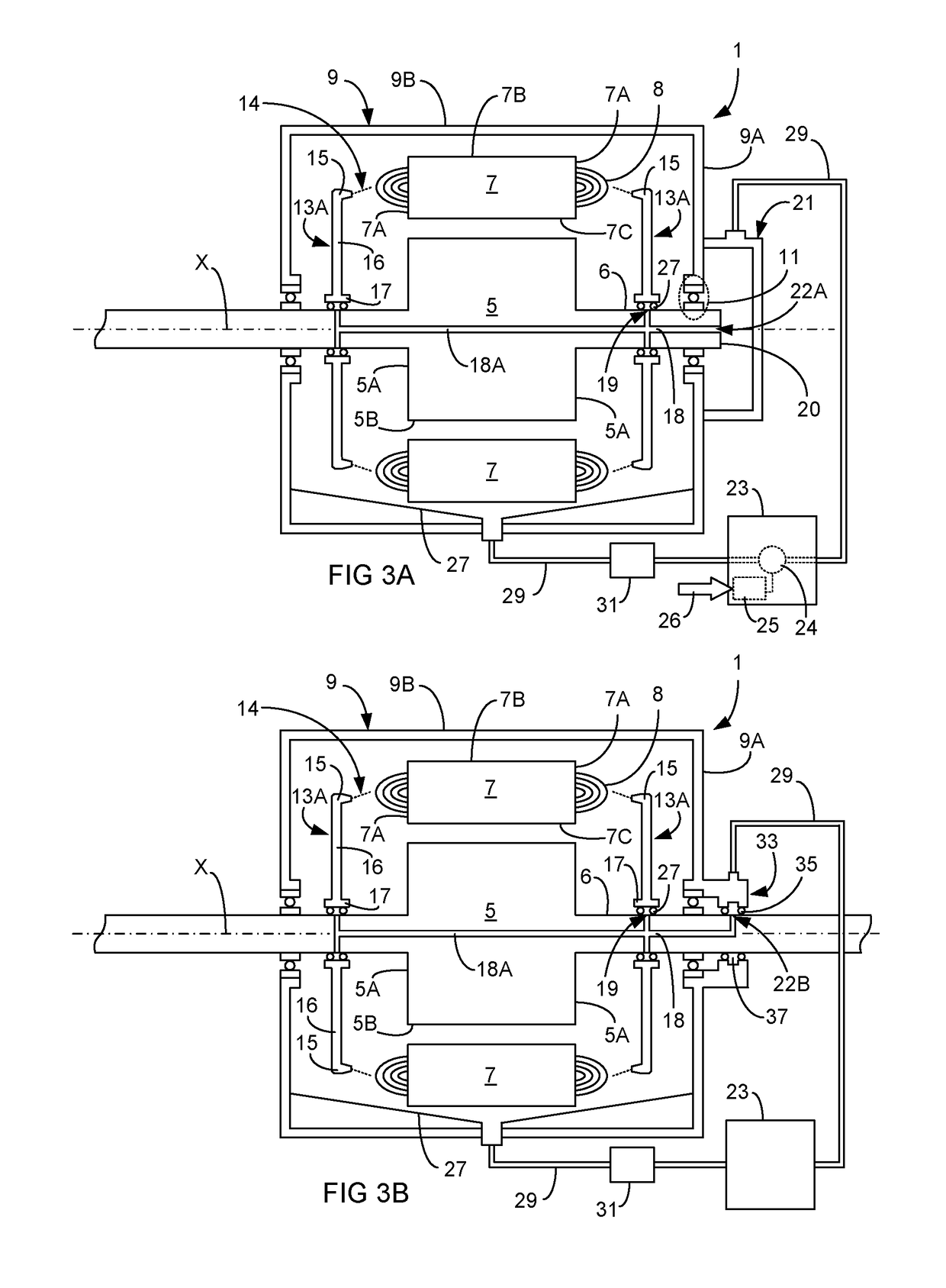
[0087]FIG. 3A illustrates a side view of an axial cross section of an electric motor substantially identical with the one that has been described above with reference to FIG. 2. Apart from the components that have been described above the electric motor 1 comprises a cooling device according to the present invention.

[0088]The cooling device comprises two cooling liquid applicators 13, arranged on a respective side of the stator / rotor module and being arranged to apply cooling liquid 14 on a respective end portion 7A of the stator 7. In more detail the two cooling liquid applicators 13 are arranged on axially opposite sides of the stator and configured to eject cooling liquid onto a respective end portion 7A of the stator from axial axially exterior positions of the stator 7. More specifically each cooling liquid applicator 13 is arranged to flush cooling liquid in the form of a substantially continuous stream onto a respective coil end 8 of the stator winding, axially extending from...

second embodiment

[0108]FIGS. 8A and 8B schematically illustrates a side view of an axial cross section of an electric motor 1 having a device for liquid cooling of the electric motor according to the present invention. The cooling device and its components is substantially similar to the cooling device and its components illustrated in FIG. 3A and FIG. 3B. A substantial difference is however the configuration of the cooling liquid applicators and the way in which they are caused to rotate relative to the stator 7 and its end portions 7A.

[0109]Like the cooling liquid applicators in the first embodiment the cooling liquid applicators 13 in this second embodiment are arranged to be caused to move by means of the rotation of the rotor shaft, but unlike therefrom the cooling liquid applicators 13 is here rotatably arranged relative to the rotor shaft 6 so that the rotational velocity of the cooling liquid applicators not necessarily need to correspond to the rotational velocity of the rotor and the rotat...


PUM


Abstract

A device for liquid cooling an electric motor having a rotor and a stator includes at least one cooling liquid applicator arranged to apply cooling liquid from the side of the stator onto an end portion of the stator. The cooling liquid applicator is moveably arranged relative to the stator so that the cooling liquid by means of the movement of the cooling liquid applicator is applied onto different areas of the end portion. In this way a continuous stream of cooling liquid can be applied onto the end portion of the stator leading to a reduced risk for erosion of located coil ends.

Description

TECHNICAL FIELD[0001]The invention relates to a device for liquid cooling of an electric motor according to the preamble of claim 1. The invention also relates to a method for liquid cooling of an electric motor according to the preamble of claim 20. The invention also relates to an electric motor comprising such device, and a motor vehicle comprising such electric motor.BACKGROUND[0002]During operation electric motors are heated whereby cooling is required to divert the heat. Cooling of electric motors can be performed using different types of cooling medium such as for example air, water or oil.[0003]In high performance electric motors cooling is extremely important in order to maintain performance. Cooling of active parts of the electric motor directly affects the performance. Hereby, liquid cooling using for example oil lead to effective cooling.[0004]An important motor component having a large need for cooling is the stator of the electric motor and in particular the end portio...

Claims


Application Information

Patent Timeline
IPC IPC(8): H02K9/193
CPCH02K9/193H02K9/19
Inventor ENGBLOM, DANIEL
Owner BAE SYSTEMS HAGGLUND AKTIEBOLAG
Why Eureka
Try Eureka